|
|
| (353 intermediate revisions by the same user not shown) |
| Line 1: |
Line 1: |
| − | ==Reverse Osmosis and Nanofiltration Systems for PFAS Removal== | + | ==Estimating PCE/TCE Abiotic First-Order Reductive Dechlorination Rate Constants in Clayey Soils Under Anoxic Conditions== |
| − | [[Wikipedia: Nanofiltration | Nanofiltration (NF)]] or [[Wikipedia: Reverse osmosis | reverse osmosis (RO)]] are engineered polymeric filters designed to remove solutes down to the atomic and molecular size scale<ref name="Wilf2019">Wilf, M., 2019. Basic Terms and Definitions, Chapter 3 in Desalination: Water from Water, 2nd Edition, J. Kucera, Editor. John Wiley & Sons. ISBN: 978-1-119-40774-4 [https://doi.org/10.1002/9781119407874.ch3 doi: 10.1002/9781119407874.ch3]</ref><ref name="BellonaEtAl2004">Bellona, C., Drewes, J., Xu, P., Amy, G., 2004. Factors affecting the rejection of organic solutes during NF/RO treatment—a literature review. Water Research, 38(12), p. 2795-2809. [https://doi.org/10.1016/j.watres.2004.03.034 doi: 10.1016/j.watres.2004.03.034]</ref><ref name="BazarganSalgado2018">Bazargan, A., Salgado, B., 2018. Fundamentals of Desalination Technology, in A Multidisciplinary Introduction to Desalination, A. Bazargan, Editor. River Publishers. p. 41-66. ISBN 9788793379541. [https://doi.org/10.1201/9781003336914 doi: 10.1201/9781003336914]</ref>. RO, and to a lesser extent NF, has been implemented in a variety of water treatment applications including seawater and brackish water desalination, surface water treatment, industrial process water separation, and purification applications<ref name="Wilf2019"/><ref name="BellonaEtAl2004"/><ref name="BazarganSalgado2018"/><ref name="TurekEtAl2017">Turek, M., Mitko, K., Piotrowski, K., Dydo, P., Laskowska, E., Jakóbik-Kolon, A., 2017. Prospects for high water recovery membrane desalination. Desalination, 401, p. 180-189. [https://doi.org/10.1016/j.desal.2016.07.047 doi: 10.1016/j.desal.2016.07.047]</ref><ref name="PanagopoulosEtAl2019">Panagopoulos, A., Haralambous, K.-J., Loizidou, M., 2019. Desalination brine disposal methods and treatment technologies - A review. Science of The Total Environment, 693, Article 133545. [https://doi.org/10.1016/j.scitotenv.2019.07.351 doi: 10.1016/j.scitotenv.2019.07.351]</ref><ref name="WarsingerEtAl2018">Warsinger, D.M., Chakraborty, S., Tow, E.W., Plumlee, M.H., Bellona, C., Loutatidou, S., Karimi, L., Mikelonis, A.M., Achilli, A., Ghassemi, A., Padhye, L.P., Snyder, S.A., Curcio, S., Vecitis, C.D., Arafat, H.A., Lienhard, J.H., 2018. A review of polymeric membranes and processes for potable water reuse. Progress in Polymer Science, 81, p. 209-237. [https://doi.org/10.1016/j.progpolymsci.2018.01.004 doi: 10.1016/j.progpolymsci.2018.01.004]</ref><ref name="Yan2017">Yan, D., 2017. Membrane Desalination Technologies, Chapter 6 in A Multidisciplinary Introduction to Desalination, A. Bazargan, Editor. River Publishers, p. 155-199. ISBN: 9788793379541</ref><ref name="Bellona2019">Bellona, C., 2019. Nanofiltration - Theory and Application, Chapter 4 in Desalination: Water from Water, 2nd Edition, J. Kucera, Editor. John Wiley & Sons. ISBN: 978-1-119-40774-4. [https://doi.org/10.1002/9781118904855.ch4 doi: 10.1002/9781118904855.ch4]</ref>. RO and NF use semi-permeable membranes that limit diffusion of solutes into the product water (i.e., permeate) through [[Wikipedia: Steric effects | steric]] and electrostatic exclusion from the membrane polymer<ref name="BellonaEtAl2004"/>. Due to the molecular size and ionic character of [[Perfluoroalkyl and Polyfluoroalkyl Substances (PFAS) | per- and polyfluoroalkyl substances (PFAS)]], past research has demonstrated that both RO and NF membranes can achieve a high degree of separation (i.e., rejection) of PFAS<ref name="ApplemanEtAl2013">Appleman, T.D., Dickenson, E.R.V., Bellona, C., Higgins, C.P., 2013. Nanofiltration and granular activated carbon treatment of perfluoroalkyl acids. Journal of Hazardous Materials, 260, p. 740-746. [https://doi.org/10.1016/j.jhazmat.2013.06.033 doi: 10.1016/j.jhazmat.2013.06.033]</ref><ref name="Steinle-DarlingReinhard2008">Steinle-Darling, E., Reinhard, M., 2008. Nanofiltration for Trace Organic Contaminant Removal: Structure, Solution, and Membrane Fouling Effects on the Rejection of Perfluorochemicals. Environmental Science and Technology, 42(14), p. 5292-5297. [https://doi.org/10.1021/es703207s doi: 10.1021/es703207s]</ref><ref name="SafulkoEtAl2023">Safulko, A., Cath, T.Y., Li, F., Tajdini, B., Boyd, M., Huehmer, R.P., Bellona, C., 2023. Rejection of perfluoroalkyl acids by nanofiltration and reverse osmosis in a high-recovery closed-circuit membrane filtration system. Separation and Purification Technology, 326, Article 124867. [https://doi.org/10.1016/j.seppur.2023.124867 doi: 10.1016/j.seppur.2023.124867] [[Media: SafulkoEtAl2023.pdf | Open Access Manuscript]]</ref>.
| + | The U.S. Department of Defense (DoD) faces many challenges in restoring aquifers at contaminated sites, often due to back-diffusion of tetrachloroethene (PCE) and trichloroethene (TCE) from low-permeability clay zones. The uptake, storage, and subsequent long-term release of these dissolved contaminants from clays are key processes in understanding the longevity, intensity, and risks associated with many persistent chlorinated ethene groundwater plumes. Although naturally occurring abiotic and biotic dechlorination processes in clays may reduce stored contaminant mass and significantly aid natural attenuation, no standardized field method currently exists to verify or quantify these reactions. It is critical to remediation design efforts to demonstrate and validate a cost-effective in situ approach for assessing these dechlorination processes using first-order rate constants. An approach was developed and applied across eight DoD sites to support Remedial Project Managers (RPMs) and regulators in evaluating natural attenuation potential in clay-rich environments. |
| | <div style="float:right;margin:0 0 2em 2em;">__TOC__</div> | | <div style="float:right;margin:0 0 2em 2em;">__TOC__</div> |
| | | | |
| | '''Related Article(s):''' | | '''Related Article(s):''' |
| | | | |
| − | *[[Perfluoroalkyl and Polyfluoroalkyl Substances (PFAS)]] | + | *[[Monitored Natural Attenuation (MNA)]] |
| − | *[[PFAS Ex Situ Water Treatment]] | + | *[[Monitored Natural Attenuation (MNA) of Chlorinated Solvents]] |
| − | *[[PFAS Sources]] | + | *[[Monitored Natural Attenuation - Transitioning from Active Remedies]] |
| − | *[[PFAS Transport and Fate]] | + | *[[Matrix Diffusion]] |
| | + | *[[REMChlor - MD]] |
| | | | |
| − | '''Contributors:''' Christopher Bellona, Nicole Masters, Stephen Richardson | + | '''Contributors:''' Dani Tran, Dr. Charles Schaefer, Dr. Charles Werth |
| | | | |
| − | '''Key Resource(s):''' | + | '''Key Resource:''' |
| − | | + | *Schaefer, C.E, Tran, D., Nguyen, D., Latta, D.E., Werth, C.J., 2025. Evaluating Mineral and In Situ Indicators of Abiotic Dechlorination in Clayey Soils<ref name="SchaeferEtAl2025"/> |
| − | *Interstate Technology Regulatory Council (ITRC), PFAS – Per- and Polyfluoroalkyl Substances: [https://pfas-1.itrcweb.org/12-treatment-technologies/#12_2 12.2 Field-Implemented Liquids Treatment Technologies] and [https://pfas-1.itrcweb.org/12-treatment-technologies/#12_5 12.5 Limited Application and Developing Liquids Treatment Technologies] | |
| | | | |
| | ==Introduction== | | ==Introduction== |
| − | [[File:RichardsonFig1.png|thumb|500px|Figure 1. Basic schematic of cross-flow operation of high-pressure membranes. The feed water flows parallel to the membrane becoming more concentrated and then leaves the system as retentate. The permeate is water forced through the membrane by applying pressure. Q is flowrate and C is concentration of the solute of interest. F is the feed, P is the permeate, and R is the retentate.]]
| + | Cost-effective methods are needed to verify the occurrence of natural dechlorination processes and quantify their dechlorination rates in clays under ambient in situ conditions in order to reliably predict their long-term influence on plume longevity and mass discharge. However, accurately determining these rates is challenging due to slow reaction kinetics, the transient nature of transformation products, and the interplay of biotic and abiotic mechanisms within the clay matrix or at clay-sand interfaces. Tools capable of quantifying these reactions and assessing their role in mitigating plume persistence would be a significant aid for long-term site management. |
| − | High-pressure membrane filtration such as nanofiltration (NF) or reverse osmosis (RO) is a filtration process that separates dissolved inorganic and organic solutes from liquid solvents, typically water<ref name="Wilf2019"/>. As opposed to porous and more permeable low-pressure membranes (i.e., microfiltration and ultrafiltration), NF and RO membranes are widely considered semi-permeable and therefore require higher operating pressures to force water against an [[Wikipedia: Osmosis | osmotic gradient]] to produce a purified permeate stream<ref name="BellonaEtAl2004"/><ref name="BazarganSalgado2018"/>. The semi-permeable nature and properties of RO and NF membranes results in significantly lower solute diffusive flux across the membranes compared to water<ref name="BellonaEtAl2004"/>.
| |
| − | | |
| − | To optimize solute separation and minimize accumulation of solutes on the membrane, these systems are almost exclusively operated in a cross-flow configuration where feed water flows parallel to the membrane surface and is forced across the membrane through the application of pressure (Figure 1). In a cross-flow configuration, NF and RO systems are separation processes that yield two streams: the treated permeate and the concentrated retentate.
| |
| − | | |
| − | Typical parameters used to describe operational performance of high-pressure membrane systems include solvent ''recovery'' and solute ''rejection''. Recovery is defined as the percentage of feed water that becomes permeate, which can be calculated as:
| |
| − | | |
| − | :::[[File: RichardsonEq1.png]]
| |
| − | | |
| − | where ''Q<sub>P</sub>'' is the permeate flow rate, and ''Q<sub>F</sub>'' is the feed flow rate. The recovery of a high-pressure membrane system is dependent upon the RO system configuration and feed water quality. For feed waters containing relatively low [[Wikipedia: Total dissolved solids | total dissolved solids (TDS)]] concentrations, in conventional RO and NF membrane applications, recovery is typically between 75% and 85%. However, several novel membrane configurations have been developed to increase membrane recoveries to 90% and greater depending on feed water quality.
| |
| − | | |
| − | Solute rejection is defined as the percent of concentrated feed water retained by the membrane and can be calculated as:
| |
| − | | |
| − | :::[[File: RichardsonEq2.png]]
| |
| − | | |
| − | where ''C<sub>p</sub>'' and ''C<sub>f</sub>'' are the concentration of a solute in the permeate and feed water, respectively. Because the retentate stream contains high concentrations of all solutes rejected by the membrane, minimization of retentate volume is a focus of ongoing research and development<ref name="TurekEtAl2017"/><ref name="PanagopoulosEtAl2019"/>.
| |
| − | | |
| − | [[File:RichardsonFig2.png|thumb|650px|Figure 2. (Left) Spiral-wound membrane element with the feed side of the element and permeate collection tube in the middle visible. (Right) 1-million gallon per day membrane system with multiple pressure vessels.]]
| |
| − | Significant advancements in membrane material development have led to development of NF and RO membranes with varying pressure requirements and solute rejection characteristics<ref name="BellonaEtAl2004"/><ref name="WarsingerEtAl2018"/>. RO utilizes very tight and selective membrane material (typically [[Wikipedia: Polyamide | polyamide]]) that can achieve high rejection of most dissolved solutes but requires relatively high pressures, typically >150 psi depending on TDS concentration and RO membrane type (e.g., requiring up to 1000 psi when treating seawater with RO membrane elements optimized for seawater)<ref name="Yan2017"/>. RO is used in a variety of applications where a high degree of solute separation is desired including seawater and brackish water desalination, potable water reuse applications, industrial water treatment, and separation applications<ref name="Wilf2019"/>. NF is fundamentally similar to RO; however, NF has been engineered to provide selective separation of solutes and often operate at lower pressures than RO (<150 psi). NF membranes have a range of rejection characteristics with some NF membranes being ‘tighter’ with lower permeability similar to RO (i.e., high salt and organic solute rejection) and others being ‘looser’ with high permeability (i.e., lower salt and organic solute rejection)<ref name="Bellona2019"/>.
| |
| | | | |
| − | High-pressure NF and RO membranes are commonly found in a spiral-wound configuration<ref name="Wilf2019"/>. Spiral-wound elements come in standardized sizes that are then loaded into a series of pressure vessels. An example of a spiral-wound element and a membrane system comprised of multiple pressure vessels is shown in Figure 2. Large-scale membrane systems are typically comprised of several membrane “stages” to increase recovery. Each stage contains multiple pressure vessels containing several individual spiral-wound elements each.
| + | For reductive abiotic dechlorination under anoxic conditions, a 1% hydrochloric acid (HCl) extraction of a sample of native clay coupled with X-ray diffraction (XRD) data can be used as a screening level tool to estimate reductive dechlorination rate constants. These rate constants can be inserted into fate and transport models such as [[REMChlor - MD]]<ref>Falta, R., and Wang, W., 2017. A semi-analytical method for simulating matrix diffusion in numerical transport models. Journal of Contaminant Hydrology, 197, pp. 39-49. [https://doi.org/10.1016/j.jconhyd.2016.12.007 doi: 10.1016/j.jconhyd.2016.12.007] [[Media: FaltaWang2017.pdf | Open Access Manuscript]]</ref><ref>Kulkarni, P.R., Adamson, D.T., Popovic, J., Newell, C.J., 2022. Modeling a well-charactized perfluorooctane sulfate (PFOS) source and plume using the REMChlor-MD model to account for matrix diffusion. Journal of Contaminant Hydrology, 247, Article 103986. [https://doi.org/10.1016/j.jconhyd.2022.103986 doi: 10.1016/j.jconhyd.2022.103986] [[Media: KulkarniEtAl2022.pdf | Open Access Manuscript]]</ref> to quantify abiotic dechlorination impacts within clay aquitards on chlorinated solvent plumes. Thus, determination of the abiotic reductive dechlorination rate constant for a particular clayey soil can be readily utilized to provide a more accurate assessment of aquifer cleanup timeframes for groundwater plumes that are being sustained by contaminant back-diffusion. |
| | | | |
| − | ==Application of High-Pressure Membranes for Treatment of PFAS Contaminated Water== | + | ==Recommended Approach== |
| − | [[File:RichardsonFig3.png|thumb|450px|Figure 3. Rejection of nine PFAAs by four available membrane products at the pilot-scale. Rejection data shown above was generated from permeate samples collected at 97% recovery.]] | + | [[File: TranFig1.png | thumb | 500 px | Figure 1: First-order rate constants for abiotic reductive dechlorination of TCE under anaerobic conditions. Circles are data from Schaefer ''et al.'', 2021<ref>Schaefer, C.E., Ho, P., Berns, E., Werth, C., 2021. Abiotic dechlorination in the presence of ferrous minerals. Journal of Contaminant Hydrology, 241, 103839. [https://doi.org/10.1016/j.jconhyd.2021.103839 doi: 10.1016/j.jconhyd.2021.103839] [[Media: SchaeferEtAl2021.pdf | Open Access Manuscript]]</ref>, filled squares from Schaefer ''et al.'', 2018<ref name="SchaeferEtAl2018"/>, and Schaefer ''et al.'', 2017<ref>Schaefer, C.E., Ho., Gurr, C., Berns, E., Werth, C., 2017. Abiotic dechlorination of chlorinated ethenes in natural clayey soils: impacts of mineralogy and temperature. Journal of Contaminant Hydrology, 206, pp. 10-17. [https://doi.org/10.1016/j.jconhyd.2017.09.007 doi: 10.1016/j.jconhyd.2017.09.007] [[Media: SchaeferEtAl2017.pdf | Open Access Manuscript]]</ref>, and open squares from Schaefer ''et al.'', 2025<ref name="SchaeferEtAl2025"/>. ]] |
| − | [[File:RichardsonFig4.png|thumb|600px|Figure 4. Mobile high-pressure membrane treatment trailer (left) and pilot-scale closed-circuit membrane filtration system (right).]]
| + | [[File: TranFig2.png | thumb | 600 px | Figure 2: Flowchart diagram of field screening procedures]] |
| − | The effectiveness of RO and NF membranes for dissolved solute rejection has led to high-pressure membranes being regarded as one of the best available technologies for PFAS removal for over a decade<ref name="ApplemanEtAl2013"/><ref name="Steinle-DarlingReinhard2008"/>. Several studies have evaluated aspects of PFAS removal by NF and RO membranes including evaluating different membrane products, the impact of operating conditions and water quality, and the influence of physicochemical characteristics of PFAS<ref name="ApplemanEtAl2013"/><ref name="SafulkoEtAl2023"/><ref name="LiuStrathmannBellona2021">Liu, C.J., Strathmann, T.J., Bellona, C., 2021. Rejection of per- and polyfluoroalkyl substances (PFASs) in aqueous film-forming foam by high-pressure membranes. Water Research, 188, Article 116546. [https://doi.org/10.1016/j.watres.2020.116546 doi: 10.1016/j.watres.2020.116546]</ref><ref name="WangEtAl2018">Wang, J., Wang, L., Xu, C., Zhi, R., Miao, R., Liang, T., Yue, X., Lv, Y., Liu, T., 2018. Perfluorooctane sulfonate and perfluorobutane sulfonate removal from water by nanofiltration membrane: The roles of solute concentration, ionic strength, and macromolecular organic foulants. Chemical Engineering Journal, 332, p. 787-797. [https://doi.org/10.1016/j.cej.2017.09.061 doi: 10.1016/j.cej.2017.09.061]</ref><ref name="ZhaoEtAl2016">Zhao, C., Tang, C.Y., Li, P., Adrian, P., Hu, G., 2016. Perfluorooctane sulfonate removal by nanofiltration membrane—the effect and interaction of magnesium ion / humic acid. Journal of Membrane Science, 503, p. 31-41. [https://doi.org/10.1016/j.memsci.2015.12.049 doi: 10.1016/j.memsci.2015.12.049]</ref><ref name="ZhaoEtAl2013">Zhao, C., Zhang, J., He, G., Wang, T., Hou, D., Luan, Z., 2013. Perfluorooctane sulfonate removal by nanofiltration membrane the role of calcium ions. Chemical Engineering Journal, 233, p. 224-232. [https://doi.org/10.1016/j.cej.2013.08.027 doi: 10.1016/j.cej.2013.08.027]</ref><ref name="Steinle-DarlingEtAl2010">Steinle-Darling, E., Litwiller, E., Reinhard, M., 2010. Effects of Sorption on the Rejection of Trace Organic Contaminants During Nanofiltration. Environmental Science and Technology, 44(7), p. 2592-2598. [https://doi.org/10.1021/es902846m doi: 10.1021/es902846m]</ref>. Most studies have focused on anionic (at neutral pH) [[Perfluoroalkyl_and_Polyfluoroalkyl_Substances_(PFAS)#Nomenclature | perfluoroalkyl acid (PFAA)]] rejection and reported greater than 90% separation of PFAAs by available NF and RO membranes due to electrostatic and steric exclusion from the membrane polymer<ref name="ApplemanEtAl2013"/><ref name="Steinle-DarlingReinhard2008"/><ref name="LiuStrathmannBellona2021"/>. Water quality constituents such as organic matter and cations including calcium and magnesium have been shown to reduce rejection of PFAS<ref name="LiuStrathmannBellona2021"/>. However, little is known about how fouling and membrane aging impact rejection of PFAS by NF and RO membranes and additional data are needed. A recent Department of Defense [https://serdp-estcp.mil/ ESTCP] pilot scale project ([https://serdp-estcp.mil/projects/details/0aa2fb20-b851-4b5b-ac64-e72795986b8a ER20-5369]) conducted at Colorado School of Mines (Mines) systematically evaluated the rejection of nine PFAAs by four available NF and RO products using full scale spiral-wound membrane elements in a high recovery membrane system which achieved up to 97% recovery<ref name="SafulkoEtAl2023"/>. Tight NF and the two RO membranes evaluated exhibited greater than 98% rejection of all PFAAs evaluated even at high recovery conditions (Figure 3). The loose NF membrane product evaluated provided lower than expected (based on literature) rejection of investigated PFAAs particularly at higher recovery values. These findings indicate that tight NF and RO membranes can be effective at separating PFAAs from contaminated source waters regardless of PFAA chain length. Energy requirements modeled from these experiments varied from 0.14 kWh/m<sup>3</sup> for loose NF to 0.57 kWh/m<sup>3</sup> for seawater RO<ref name="SafulkoEtAl2023"/>.
| + | The recommended approach builds upon the methodology and findings of a recent study<ref name="SchaeferEtAl2025">Schaefer, C.E., Tran, D., Nguyen, D., Latta, D.E., Werth, C.J., 2025. Evaluating Mineral and In Situ Indicators of Abiotic Dechlorination in Clayey Soils. Groundwater Monitoring and Remediation, 45(2), pp. 31-39. [https://doi.org/10.1111/gwmr.12709 doi: 10.1111/gwmr.12709]</ref>, emphasizing field-based and analytical techniques to quantify abiotic first-order reductive dechlorination rate constants for PCE and TCE in clayey soils under anoxic conditions. Key components of this evaluation are listed below: |
| | + | #<u>Zone Identification:</u> The focus of the investigation should be to delineate clayey zones adjacent to hydraulically conductive zones. |
| | + | #<u>Ferrous Mineral Quantification:</u> Assess ferrous mineral context in clay via 1% HCl extraction at ambient temperature over a 10-minute interval. |
| | + | #<u>Mineralogical Characterization:</u> Conduct XRD analysis with the specific intent of identifying the presence of pyrite and biotite. |
| | + | #<u>Reduced Gas Analysis:</u> Measurement of reduced gases such as acetylene, ethene, and ethane concentrations in clay samples. Gas-tight sampling devices (e.g., En Core® soil samplers by En Novative Technologies, Inc.) should be used to ensure sample integrity during collection and transport. |
| | | | |
| − | Mines researchers have developed a mobile high-recovery closed-circuit membrane filtration system (Figure 4) that has been successfully deployed for treating groundwater at a fire training area of Wright-Patterson Air Force Base ([https://serdp-estcp.mil/projects/details/be0417c9-aaa4-4fd6-9007-7de0cdbffb85 ESTCP ER21-5136]), groundwater at Peterson Space Force Base (AFCEC BAA-031), and firetruck rinsate at Tyndall Air Force Base ([https://serdp-estcp.mil/projects/details/0aa2fb20-b851-4b5b-ac64-e72795986b8a ESTCP ER20-5369]) during recent ESTCP and AFCEC funded research projects. In these projects, NF or RO was implemented to produce a permeate stream containing low concentrations of PFAS and to concentrate PFAS into smaller volumes of retentate for subsequent destructive PFAS treatment. While NF and RO membranes have demonstrated effective rejection of PFAS, PFAS are subsequently concentrated in the membrane concentrate, or retentate stream. This concentrate stream is increasingly paired with PFAS destruction technologies, as PFAS destruction is often considered viable only for concentrated solutions of PFAS. Ongoing ESTCP funded projects include using high-recovery NF and RO to treat and concentrate groundwater leading to PFAS destruction using [[PFAS Treatment by Electrical Discharge Plasma | plasma based treatment]]<ref name="Richardson2021"> Richardson, S., 2021. Nanofiltration Followed by Electrical Discharge Plasma for Destruction of PFAS and Co-occurring Chemicals in Groundwater: A Treatment Train Approach. [https://serdp-estcp.mil/ Environmental Security Technology Certification Program (ESTCP)], [https://serdp-estcp.mil/projects/details/be0417c9-aaa4-4fd6-9007-7de0cdbffb85/er21-5136-project-overview Project ER21-5136]</ref> or [[Hydrothermal Alkaline Treatment (HALT) | hydrothermal alkaline treatment (HALT)]]<ref name="Bellona2023">Bellona, C., 2023. Cradle to Grave PFAS Treatment Using Membrane and Foam Fractionation Concentration Followed by Hydrothermal Alkaline Treatment. [https://serdp-estcp.mil/ Environmental Security Technology Certification Program (ESTCP)], [https://serdp-estcp.mil/projects/details/5cf08cdb-b86a-45d2-98d3-f747ba97d293 Project ER23-8367]</ref>.
| + | Clay samples should be collected within a few centimeters of the high-permeability interface, with optional additional sampling further inward. For mineralogical analysis, a defined interval may be collected and subsequently subsampled. To preserve sample integrity, exposure to air should be minimized during collection, transport, and handling. Homogenization should occur within an anaerobic chamber, and if subsamples are required for external analysis, they must be shipped in gas-tight, anaerobic containers. |
| | | | |
| − | ==Advantages and Limitations of the Technology for PFAS Removal==
| + | Estimation of the abiotic reductive first-order rate constant for PCE and TCE is based on the “reactive” ferrous content in the clay. Reactive ferrous content (Fe(II)<sub>r</sub>) is estimated as shown in Equation 1: |
| − | <u>Advantages:</u> | |
| − | *Robust, high throughput treatment
| |
| − | *Mature technology with well documented solute separation performance
| |
| − | *High rejection of PFAS and other contaminants
| |
| − | *Removes solutes at the molecular scale
| |
| | | | |
| − | <u>Limitations:</u> | + | ::'''Equation 1:''' <big>''Fe(II)<sub><small>r</small></sub> = DA + XRD<sub><small>pyr</small></sub> - XRD<sub><small>biotite</small></sub>''</big> |
| − | *Complex and often expensive pretreatment requirements for certain waters
| |
| − | *Energy intensive
| |
| − | *High capital costs
| |
| − | *Membrane fouling requiring high chemical usage for cleaning
| |
| − | *Concentrated waste stream requiring disposal or destruction
| |
| − | *Permeate quality depends on feed water concentration
| |
| − | *Greater operation complexity than most water treatment processes
| |
| − | *Water loss due to membrane separation
| |
| | | | |
| − | ==Summary== | + | where ''DA'' is the ferrous content from the dilute acid (1% HCl) extraction, ''XRD<sub><small>pyr</small></sub>'' is the pyrite content from XRD analysis, and ''XRD<sub><small>biotite</small></sub>'' is the biotite content from XRD analysis<ref name="SchaeferEtAl2025"/>. |
| | | | |
| | + | Abiotic dechlorination is unlikely to contribute to mitigating contaminant back-diffusion when reactive ferrous iron (Fe(II)<sub><small>r</small></sub>) concentrations are below 100 mg/kg (Figure 1). For Fe(II)<sub><small>r</small></sub> above 100 mg/kg, the first-order rate constant for PCE and TCE reductive dechlorination can be estimated using the correlation shown in Figure 1<ref name="SchaeferEtAl2018">Schaefer, C.E., Ho, P., Berns, E., Werth, C., 2018. Mechanisms for abiotic dechlorination of trichloroethene by ferrous minerals under oxic and anoxic conditions in natural sediments. Environmental Science and Technology, 52(23), pp.13747-13755. [https://doi.org/10.1021/acs.est.8b04108 doi: 10.1021/acs.est.8b04108]</ref><ref>Borden, R.C., Cha, K.Y., 2021. Evaluating the impact of back diffusion on groundwater cleanup time. Journal of Contaminant Hydrology, 243, Article 103889. [https://doi.org/10.1016/j.jconhyd.2021.103889 doi: 10.1016/j.jconhyd.2021] [[Media: BordenCha2021.pdf | Open Access Manuscript]]</ref>. The rate constant exhibits a strong positive correlation with the logarithm of reactive Fe(II) content (Pearson’s ''r'' = 0.82), with a slope of 4.7 × 10⁻⁸ L g⁻¹ d⁻¹ (log mg kg⁻¹)⁻¹. |
| | | | |
| − | This investigation proposes that PCMs can affect the thermodynamics and kinetics of hydrolysis reactions by confining the reaction species near PCM surfaces, thus making them less accessible to solvent molecules and creating an environment with a weaker dielectric constant that favors nucleophilic substitution reactions. The addition of QA groups on the PCM surface can further accelerate MC hydrolysis. The performance of PCM toward DNAN hydrolysis was evaluated by comparing the MC decay kinetics across various PCM types, including unmodified PCMs such as almond shell char or activated carbon (AC)), and modified PCMs with physical or chemically attached QA groups. The results suggest that QA-modified activated carbon performed the best by reducing the half-life of DNAN to 2.5 days at pH 11.5 and 25°C while maintaining its reactivity over ten consecutive additions of DNAN<ref name="SeenthiaEtAl2024"/>. TNT exhibited faster decay in samples containing QA-modified AC than unmodified AC, with an estimated half-life of 0.2 days and 1 day, respectively<ref name="Li"/>. Nitrite was observed as one of the transformation products for both DNAN and TNT, suggesting the presence of PCM favored the denitration pathway. By contrast, demethylation, the preferred pathway in homogeneous solution, produces [[Wikipedia: 2,4-Dinitrophenol | 2,4-dinitrophenol (DNP)]]. Denitration catalyzed by PCM was advantageous when compared to demethylation because nitrite is less toxic than DNAN and DNP. Overall, the results suggest that further improvement of the PCM performance could be expected by tailoring its surface to increase the abundance of QA while decreasing the presence of -NH<sub>2</sub> or -OH groups for the hydrolysis of MCs.
| + | Figure 2 presents a decision flowchart designed to evaluate the significance and extent of abiotic reductive dechlorination. By applying Equation 1 to the dilute acid extractable Fe(II) plus measured mineral species data from clay samples, the reactive ferrous iron content (Fe(II)<sub><small>r</small></sub>) can be quantified, enabling a streamlined assessment of the extent to which abiotic processes are contributing to the mitigation of contaminant back-diffusion. |
| | | | |
| − | [[File:XuFig3.png | thumb |400px| Figure 3. (a) Ball-and-stick model of TNT confined between four layers of graphene with quaternary ammonium groups with a 4-nm distance, black = graphite, green = TNT, purple = ammonium groups, orange = chloride ions, blue = hydroxide oxygens<ref name="SeenthiaEtAl2024"/>. (b) (Top) Molecular snapshot from an AIMD/MM simulation: DNAN + [OH<sup>-</sup>] → DNAN-2-OH + nitrite in a nano-pore, containing DNAN, hydroxide, Na<sup>+</sup> counter-ion, and 43 H<sub>2</sub>O, at a concentration of 1.3 M. (Bottom) Reaction pathways: Nucleophilic aromatic reaction of DNAN + [OH<sup>-</sup>] → DNAN-2-OH + Nitrite in solution and within a nano-pore, investigated using PBE and PBE0 AIMD/MM free energy simulations with WHAM. Each pathway used approximately 0.5 ns of simulation time<ref name="Li"/>.]]
| + | If Fe(II)r is ≥ 100 mg/kg, a first-order dechlorination rate constant can be estimated and subsequently used within a contaminant fate and transport model. However, if acetylene is detected in the clay, even with Fe(II)r less than 100 mg/kg, then bench-scale testing using methods similar to those described in a recent study<ref name="SchaeferEtAl2025"/> is recommended, as such results would likely be inconsistent with those shown in Figure 1, suggesting some other mechanism might be involved, or that the system mineralogy might be more complex than anticipated. Even if Fe(II)r ≥ 100 mg/kg, confirmatory bench-scale testing may be conducted for additional verification and to refine estimation of the abiotic dechlorination rate constant. |
| − | Further mechanistic insights were obtained by performing non-reactive molecular dynamics simulations on idealized pore structures. Upon the introduction of positively charged QA groups, the structure changed dramatically at the PCM interface. As the number of surface groups increased, the resulting density of OH<sup>-</sup> at the PCM surface increased by a factor of four relative to the density in the middle of the pore. Hence, the impact of the surface-bound cations was to attract OH<sup>-</sup> in competition with the neutralizing anions in the environment. In addition to driving the accumulation of OH<sup>-</sup>, the surface QA groups also impacted the distribution of TNT in the pore. At low QA surface coverage, TNT sought to adsorb on the exposed graphene. However, at sufficiently high QA surface coverage, TNT was blocked from lying flat on the graphene sheet and instead aggregated in the fluid away from the pore wall. The observation of TNT surface layering at intermediate charge densities was intriguing because it demonstrated the collection of TNT molecules close to the surface in the same spatial region where hydroxide was likewise accumulating relative to its concentration in the interstitial fluid. The molecular dynamics simulations provided evidence that the presence of the surface groups can play a role in accelerating TNT hydrolysis by acting to concentrate both TNT and hydroxide near the pore wall<ref name="Li"/>.
| |
| | | | |
| − | [[Wikipedia: Molecular dynamics#Potentials in ab initio methods | ''Ab Initio'' Molecular Dynamics/Molecular Mechanics (AIMD/MM)]] free energy simulations using expanded slabs and unit cells were also performed, focusing on the interaction of DNAN, hydroxide ions, Na<sup>+</sup>, and multiple water molecules sandwiched between two graphene layers<ref name="SeenthiaEtAl2024"/>. The upper panel of Figure 3(b) provides a molecular snapshot from the AIMD/MM simulation, showcasing the intermediate stage of DNAN reacting with a hydroxide ion within a nano-pore structure. The lower panel depicts the reaction energy profiles for the hydrolysis of DNAN, both in bulk aqueous solution and within the nano-pore environment. The x-axis represents the reaction coordinate, a schematic representation of the progression from reactants to products through various transition states and intermediates. The y-axis corresponds to the [[Wikipedia: Gibbs free energy| Gibbs free energy]] changes (ΔG), providing insights into the thermodynamic favorability of each step in the pathway. Lower barriers corresponded to more kinetically accessible reactions. In the nano-pore environment, the energy barriers were significantly reduced, suggesting a catalytic effect due to confinement. This reduction was quantified by a decrease in ΔG of approximately 8 kcal/mol compared to the bulk solution, indicating that the reactions were not only more thermodynamically favorable but also kinetically accelerated in the nano-pore. In conclusion, the results demonstrate that nano-pore environments can significantly alter the hydrolysis mechanism of DNAN, leading to potentially less toxic products.
| + | ==Summary and Recommendations== |
| | + | The approach outlined above is intended to serve as a generalized guide for practitioners and site managers to cost-effectively determine the extent to which beneficial abiotic reductive dechlorination reactions are likely occurring in low permeability (e.g., clayey) zones. This approach may be contraindicated if co-contaminants are present. It is currently unclear whether other classes of potentially reactive chemicals, such as trinitrotoluene (TNT) or chlorinated ethanes, could interact competitively with PCE and TCE. |
| | | | |
| − | [[File:XuFig4.png | thumb |500px| Figure 4. Proposed formation of charge-assisted hydrogen bond between NTO and weak acid functional groups on the carbon surface<ref name="Abdelraheem"/>.]]
| + | In addition, it remains unclear how other classes of compounds such as per- and polyfluoroalkyl substances (PFAS) may interact or sorb with ferrous minerals and potentially inhibit abiotic dechlorination reactions. Coupling these recommended activities with conventional site investigation tasks would provide an opportunity to perform many of the up-front screening activities with minimal additional project costs. It is important to note that the guidance proposed herein pertains to particularly low permeability media. Sites with complex or varying lithology, where the mineralogy and/or redox conditions may vary, might require evaluation of multiple samples to provide appropriate site-wide information. |
| − | Results from this project suggest that NTO was chemically stable for up to at least a week in NaOH solution at pH 13.8<ref name="Abdelraheem">Abdelraheem, W., Meng, L., Pignatello, J.J., Seenthia, N.I., Xu, W., 2024. Participation of Strong H-Bonding to Acidic Groups Contributes to the Intense Sorption of the Anionic Munition, Nitrotriazolone (NTO) to the Carbon, Filtrasorb 400. Environmental Science and Technology, 58(46), pp. 20719-20728. [https://doi.org/10.1021/acs.est.4c07055 doi: 10.1021/acs.est.4c07055]</ref>. Despite its highly polar and anionic character (''pK<sub>a</sub>'' = 3.78), NTO exhibited unexpectedly strong sorption toward PCM at environmentally relevant pH conditions. This high affinity was partly due to the formation of an exceptionally strong negative charge-assisted hydrogen bond, or (−)CAHB, with weak acid functional groups on the carbon surface. The CAHB was identified by evaluating adsorption isotherms, pH adsorption edge plots, competitive sorption experiments, and pH drift experiments. The findings contradict the conventional view that polar organic anions have little affinity for or are even repelled by hydrophobic carbonaceous sorbents. The results call attention to the need for new models or modification of existing models for the sorption of ionizable compounds that consider CAHB formation with sorbents. The findings also have potential implications for the use of carbons in environmental remediation and catalysis, particularly for the design of strategies for the retention and degradation of highly mobile contaminants.
| |
| | | | |
| − | Batch and column tests were conducted to evaluate the adsorption and hydrolysis of post-detonation residues of [[Wikipedia: IMX-101 | IMX-101]] in three DoD range soils amended with modified PCMs<ref name="SeenthiaEtAl2025">Seenthia, N.I., Abdelraheem, W., Beal, S.A., Pignatello, J.J., Xu, W., 2025. Simultaneous adsorption and hydrolysis of insensitive munition compounds by pyrogenic carbonaceous matter (PCM) and functionalized PCM in soils. Journal of Hazardous Materials, 494, article 138501. [https://doi.org/10.1016/j.jhazmat.2025.138501 doi: 10.1016/j.jhazmat.2025.138501]</ref>. Results indicated that adding PCMs enhanced the removal of NTO, NQ, and DNAN in soils compared to the soil controls, with enhancement factors ranging from 50 to 300. Consistent with previous results, NTO exhibited the highest partition coefficients (''K<sub>d</sub>'') in PCM-amended soils compared to DNAN and NQ despite its highly polar and anionic character. Among various PCMs, QA-modified AC performed best, followed by unmodified AC and chars. The ''K<sub>d</sub>'' values of NTO, NQ, and DNAN were slightly lower in the IMX-101 mixture than individually, possibly due to the adsorption competition from other constituents in IMX-101. The treatment was evaluated at pH 8, 10, and 12. No NTO decay was observed across the investigated pH range with or without PCM. By contrast, up to 13% of NQ was removed but only at pH > 10. Up to 90% DNAN decay occurred at pH 10 and 12 over 7 days in soils amended with modified AC. The 2% amendment dose was most effective, maintaining its adsorption capacity and reactivity over three consecutive IMX-101 additions. Column tests confirmed that 2% PCM addition significantly delayed the NTO, NQ, and DNAN breakthrough. The breakthrough volume (defined as treatment volume resulting in Concentration<sub>out</sub>=0.1*Concentration<sub>in</sub>) of NTO, NQ, and DNAN correlated with their ''K<sub>d</sub>'' values obtained from the batch tests, where no retention was observed in the absence of PCM amendments. These findings highlight the feasibility of using modified PCM to simultaneously retain and transform IMX residues, providing a strategy for using reactive amendments ''in situ'' to sustain military operation and pollutant abatement.
| + | <br clear="right"/> |
| | | | |
| | ==References== | | ==References== |
| Line 82: |
Line 55: |
| | | | |
| | ==See Also== | | ==See Also== |
| | + | *[https://serdp-estcp.mil/projects/details/a7e3f7b5-ed82-4591-adaa-6196ff33dd60 ESTCP Project ER20-5031 – In Situ Verification and Quantification of Naturally Occurring Dechlorination Rates in Clays: Demonstrating Processes that Mitigate Back-Diffusion and Plume Persistence] |
Estimating PCE/TCE Abiotic First-Order Reductive Dechlorination Rate Constants in Clayey Soils Under Anoxic Conditions
The U.S. Department of Defense (DoD) faces many challenges in restoring aquifers at contaminated sites, often due to back-diffusion of tetrachloroethene (PCE) and trichloroethene (TCE) from low-permeability clay zones. The uptake, storage, and subsequent long-term release of these dissolved contaminants from clays are key processes in understanding the longevity, intensity, and risks associated with many persistent chlorinated ethene groundwater plumes. Although naturally occurring abiotic and biotic dechlorination processes in clays may reduce stored contaminant mass and significantly aid natural attenuation, no standardized field method currently exists to verify or quantify these reactions. It is critical to remediation design efforts to demonstrate and validate a cost-effective in situ approach for assessing these dechlorination processes using first-order rate constants. An approach was developed and applied across eight DoD sites to support Remedial Project Managers (RPMs) and regulators in evaluating natural attenuation potential in clay-rich environments.
Related Article(s):
Contributors: Dani Tran, Dr. Charles Schaefer, Dr. Charles Werth
Key Resource:
- Schaefer, C.E, Tran, D., Nguyen, D., Latta, D.E., Werth, C.J., 2025. Evaluating Mineral and In Situ Indicators of Abiotic Dechlorination in Clayey Soils[1]
Introduction
Cost-effective methods are needed to verify the occurrence of natural dechlorination processes and quantify their dechlorination rates in clays under ambient in situ conditions in order to reliably predict their long-term influence on plume longevity and mass discharge. However, accurately determining these rates is challenging due to slow reaction kinetics, the transient nature of transformation products, and the interplay of biotic and abiotic mechanisms within the clay matrix or at clay-sand interfaces. Tools capable of quantifying these reactions and assessing their role in mitigating plume persistence would be a significant aid for long-term site management.
For reductive abiotic dechlorination under anoxic conditions, a 1% hydrochloric acid (HCl) extraction of a sample of native clay coupled with X-ray diffraction (XRD) data can be used as a screening level tool to estimate reductive dechlorination rate constants. These rate constants can be inserted into fate and transport models such as REMChlor - MD[2][3] to quantify abiotic dechlorination impacts within clay aquitards on chlorinated solvent plumes. Thus, determination of the abiotic reductive dechlorination rate constant for a particular clayey soil can be readily utilized to provide a more accurate assessment of aquifer cleanup timeframes for groundwater plumes that are being sustained by contaminant back-diffusion.
Recommended Approach
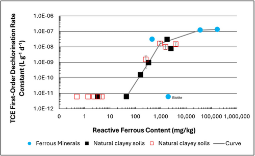
Figure 1: First-order rate constants for abiotic reductive dechlorination of TCE under anaerobic conditions. Circles are data from Schaefer
et al., 2021
[4], filled squares from Schaefer
et al., 2018
[5], and Schaefer
et al., 2017
[6], and open squares from Schaefer
et al., 2025
[1].
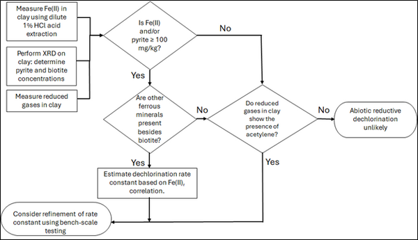
Figure 2: Flowchart diagram of field screening procedures
The recommended approach builds upon the methodology and findings of a recent study[1], emphasizing field-based and analytical techniques to quantify abiotic first-order reductive dechlorination rate constants for PCE and TCE in clayey soils under anoxic conditions. Key components of this evaluation are listed below:
- Zone Identification: The focus of the investigation should be to delineate clayey zones adjacent to hydraulically conductive zones.
- Ferrous Mineral Quantification: Assess ferrous mineral context in clay via 1% HCl extraction at ambient temperature over a 10-minute interval.
- Mineralogical Characterization: Conduct XRD analysis with the specific intent of identifying the presence of pyrite and biotite.
- Reduced Gas Analysis: Measurement of reduced gases such as acetylene, ethene, and ethane concentrations in clay samples. Gas-tight sampling devices (e.g., En Core® soil samplers by En Novative Technologies, Inc.) should be used to ensure sample integrity during collection and transport.
Clay samples should be collected within a few centimeters of the high-permeability interface, with optional additional sampling further inward. For mineralogical analysis, a defined interval may be collected and subsequently subsampled. To preserve sample integrity, exposure to air should be minimized during collection, transport, and handling. Homogenization should occur within an anaerobic chamber, and if subsamples are required for external analysis, they must be shipped in gas-tight, anaerobic containers.
Estimation of the abiotic reductive first-order rate constant for PCE and TCE is based on the “reactive” ferrous content in the clay. Reactive ferrous content (Fe(II)r) is estimated as shown in Equation 1:
- Equation 1: Fe(II)r = DA + XRDpyr - XRDbiotite
where DA is the ferrous content from the dilute acid (1% HCl) extraction, XRDpyr is the pyrite content from XRD analysis, and XRDbiotite is the biotite content from XRD analysis[1].
Abiotic dechlorination is unlikely to contribute to mitigating contaminant back-diffusion when reactive ferrous iron (Fe(II)r) concentrations are below 100 mg/kg (Figure 1). For Fe(II)r above 100 mg/kg, the first-order rate constant for PCE and TCE reductive dechlorination can be estimated using the correlation shown in Figure 1[5][7]. The rate constant exhibits a strong positive correlation with the logarithm of reactive Fe(II) content (Pearson’s r = 0.82), with a slope of 4.7 × 10⁻⁸ L g⁻¹ d⁻¹ (log mg kg⁻¹)⁻¹.
Figure 2 presents a decision flowchart designed to evaluate the significance and extent of abiotic reductive dechlorination. By applying Equation 1 to the dilute acid extractable Fe(II) plus measured mineral species data from clay samples, the reactive ferrous iron content (Fe(II)r) can be quantified, enabling a streamlined assessment of the extent to which abiotic processes are contributing to the mitigation of contaminant back-diffusion.
If Fe(II)r is ≥ 100 mg/kg, a first-order dechlorination rate constant can be estimated and subsequently used within a contaminant fate and transport model. However, if acetylene is detected in the clay, even with Fe(II)r less than 100 mg/kg, then bench-scale testing using methods similar to those described in a recent study[1] is recommended, as such results would likely be inconsistent with those shown in Figure 1, suggesting some other mechanism might be involved, or that the system mineralogy might be more complex than anticipated. Even if Fe(II)r ≥ 100 mg/kg, confirmatory bench-scale testing may be conducted for additional verification and to refine estimation of the abiotic dechlorination rate constant.
Summary and Recommendations
The approach outlined above is intended to serve as a generalized guide for practitioners and site managers to cost-effectively determine the extent to which beneficial abiotic reductive dechlorination reactions are likely occurring in low permeability (e.g., clayey) zones. This approach may be contraindicated if co-contaminants are present. It is currently unclear whether other classes of potentially reactive chemicals, such as trinitrotoluene (TNT) or chlorinated ethanes, could interact competitively with PCE and TCE.
In addition, it remains unclear how other classes of compounds such as per- and polyfluoroalkyl substances (PFAS) may interact or sorb with ferrous minerals and potentially inhibit abiotic dechlorination reactions. Coupling these recommended activities with conventional site investigation tasks would provide an opportunity to perform many of the up-front screening activities with minimal additional project costs. It is important to note that the guidance proposed herein pertains to particularly low permeability media. Sites with complex or varying lithology, where the mineralogy and/or redox conditions may vary, might require evaluation of multiple samples to provide appropriate site-wide information.
References
- ^ 1.0 1.1 1.2 1.3 1.4 Schaefer, C.E., Tran, D., Nguyen, D., Latta, D.E., Werth, C.J., 2025. Evaluating Mineral and In Situ Indicators of Abiotic Dechlorination in Clayey Soils. Groundwater Monitoring and Remediation, 45(2), pp. 31-39. doi: 10.1111/gwmr.12709
- ^ Falta, R., and Wang, W., 2017. A semi-analytical method for simulating matrix diffusion in numerical transport models. Journal of Contaminant Hydrology, 197, pp. 39-49. doi: 10.1016/j.jconhyd.2016.12.007 Open Access Manuscript
- ^ Kulkarni, P.R., Adamson, D.T., Popovic, J., Newell, C.J., 2022. Modeling a well-charactized perfluorooctane sulfate (PFOS) source and plume using the REMChlor-MD model to account for matrix diffusion. Journal of Contaminant Hydrology, 247, Article 103986. doi: 10.1016/j.jconhyd.2022.103986 Open Access Manuscript
- ^ Schaefer, C.E., Ho, P., Berns, E., Werth, C., 2021. Abiotic dechlorination in the presence of ferrous minerals. Journal of Contaminant Hydrology, 241, 103839. doi: 10.1016/j.jconhyd.2021.103839 Open Access Manuscript
- ^ 5.0 5.1 Schaefer, C.E., Ho, P., Berns, E., Werth, C., 2018. Mechanisms for abiotic dechlorination of trichloroethene by ferrous minerals under oxic and anoxic conditions in natural sediments. Environmental Science and Technology, 52(23), pp.13747-13755. doi: 10.1021/acs.est.8b04108
- ^ Schaefer, C.E., Ho., Gurr, C., Berns, E., Werth, C., 2017. Abiotic dechlorination of chlorinated ethenes in natural clayey soils: impacts of mineralogy and temperature. Journal of Contaminant Hydrology, 206, pp. 10-17. doi: 10.1016/j.jconhyd.2017.09.007 Open Access Manuscript
- ^ Borden, R.C., Cha, K.Y., 2021. Evaluating the impact of back diffusion on groundwater cleanup time. Journal of Contaminant Hydrology, 243, Article 103889. doi: 10.1016/j.jconhyd.2021 Open Access Manuscript
See Also

