|
|
| (590 intermediate revisions by the same user not shown) |
| Line 1: |
Line 1: |
| − | ==PFAS Treatment by Anion Exchange== | + | ==Estimating PCE/TCE Abiotic First-Order Reductive Dechlorination Rate Constants in Clayey Soils Under Anoxic Conditions== |
| − | <center>
| + | The U.S. Department of Defense (DoD) faces many challenges in restoring aquifers at contaminated sites, often due to back-diffusion of tetrachloroethene (PCE) and trichloroethene (TCE) from low-permeability clay zones. The uptake, storage, and subsequent long-term release of these dissolved contaminants from clays are key processes in understanding the longevity, intensity, and risks associated with many persistent chlorinated ethene groundwater plumes. Although naturally occurring abiotic and biotic dechlorination processes in clays may reduce stored contaminant mass and significantly aid natural attenuation, no standardized field method currently exists to verify or quantify these reactions. It is critical to remediation design efforts to demonstrate and validate a cost-effective in situ approach for assessing these dechlorination processes using first-order rate constants. An approach was developed and applied across eight DoD sites to support Remedial Project Managers (RPMs) and regulators in evaluating natural attenuation potential in clay-rich environments. |
| − | {| id="mp-middle" style="margin:auto; width: 95%; margin-top:3px; border-spacing: 0px; "
| |
| − | |-
| |
| − | |
| |
| − | {| id="mp-left" style="width:60%; margin:4px 0; background:none; border-spacing: 0px;"
| |
| − | | style="border:1px solid transparent; " |
| |
| − | | class="MainPageBG" style="border:1px solid #cedff2; background:#f5faff; vertical-align:top;" |
| |
| − | {| id="mp-left" style="width:100%; vertical-align:top; background:#f5faff;"
| |
| − | |-
| |
| − | | style="padding:2px; width:100%" |<h2 id="mp-otd-h2" style="margin:3px; background:#cedff2; font-family:inherit; font-size:120%; font-weight:bold; border:1px solid #a3b0bf; text-align:left; color:#000; padding:0.2em 0.4em;">Editorial Board</h2>
| |
| − | |-
| |
| − | | colspan="3" |
| |
| − | ----
| |
| − | <!-- {| style="margin: left; text-align:left;" -->
| |
| − | |-
| |
| − | | colspan="3" |<span style="line-height: 1em;">'''Editor-in-Chief'''<br /><span style="line-height: 1.2em;">[[Dr. Robert Borden, P.E.|Robert C. Borden, PhD, PE]]
| |
| − | |-
| |
| − | | colspan="3" |
| |
| − | ----
| |
| − | |-
| |
| − | |}
| |
| − | {|
| |
| − | |-
| |
| − | ||'''Editors'''
| |
| − | | style="width:40px;" | ||
| |
| − | |-
| |
| − | ||<span style="line-height: 1.1em;">[[Dr. Jason Barnes|Jason Barnes, PhD]]<br />Cascadia College || ||[[Dr. Samuel Beal|Samuel Beal, PhD]]<br />CRREL Research and Development Center
| |
| − | |-
| |
| − | || || ||
| |
| − | |-
| |
| − | ||<span style="line-height: 1.1em;">[[Craig E. Divine, Ph.D., PG|Craig E. Divine, PhD, PG]]<br />Arcadis || ||[[Dr. Kevin Finneran|Kevin Finneran, PhD]]<br />Finneran Environmental, LLC
| |
| − | |-
| |
| − | || || ||
| |
| − | |-
| |
| − | ||<span style="line-height: 1.1em;">[[Dr. Upal Ghosh|Upal Ghosh, PhD]]<br />University of Maryland, Baltimore County || ||[[Dr. Rao Kotamarthi| Rao Kotamarthi, PhD]]<br />Argonne National Lab
| |
| − | |-
| |
| − | || || ||
| |
| − | |-
| |
| − | ||<span style="line-height: 1.1em;">[[Kim Matthews| Kim Matthews]]<br />RTI International || ||[[Dr. Charles Newell, P.E.|Charles Newell, PhD, PE]]<br />GSI Environmental
| |
| − | |-
| |
| − | || || ||
| |
| − | |-
| |
| − | ||<span style="line-height: 1.1em;"> [[Dr. Alexandra Salter-Blanc|Alexandra Salter-Blanc, PhD]]<br />Jacobs || ||[[Dr. John Wilson|John Wilson, PhD]]<br />Scissortail Environmental Solutions, LLC
| |
| − | |}
| |
| − | | style="width:20px;" |
| |
| − | |
| |
| − | {| id="mp-left" style="width:400px; margin:4px 0 0 0; background:none; border-spacing: 0px;"
| |
| − | | style="border:1px solid transparent; " |
| |
| − | | class="MainPageBG" style="border:1px solid #cedff2; background:#f5faff; vertical-align:top;" |
| |
| − | {| id="mp-left" style="width:100%; vertical-align:top; background:#f5faff;"
| |
| − | |-
| |
| − | | style="padding:2px; width:100%" |<h2 id="mp-otd-h2_2" style="margin:3px; background:#cedff2; font-family:inherit; font-size:120%; font-weight:bold; border:1px solid #a3b0bf; text-align:left; color:#000; padding:0.2em 0.4em;">Development Team</h2>
| |
| − | |-
| |
| − | |
| |
| − | ----
| |
| − | |-
| |
| − | |'''Executive Editor'''
| |
| − | |-
| |
| − | |Bilgen Yuncu, PhD, PE
| |
| − | |-
| |
| − | |TRC, Cary NC
| |
| − | |-
| |
| − | |
| |
| − | ----
| |
| − | |-
| |
| − | ||
| |
| − | |-
| |
| − | ||
| |
| − | |-
| |
| − | |''Technical Editor''
| |
| − | |-
| |
| − | |Jim Hurley, MS, EIT
| |
| − | |-
| |
| − | |TRC, Cary NC
| |
| − | |-
| |
| − | ||
| |
| − | |-
| |
| − | ||
| |
| − | |-
| |
| − | |''Administrative Assistant''
| |
| − | |-
| |
| − | |Debra Tabron
| |
| − | |-
| |
| − | |TRC, Cary NC
| |
| − | |-
| |
| − | ||
| |
| − | |}
| |
| − | |}
| |
| − | |}
| |
| − | |}
| |
| − | </center>
| |
| − | | |
| − | [[Wikipedia: Ion exchange | Anion exchange]] has emerged as one of the most effective and economical technologies for treatment of water contaminated by [[Perfluoroalkyl and Polyfluoroalkyl Substances (PFAS) | per- and polyfluoroalkyl substances (PFAS)]]. Anion exchange resins (AERs) are polymer beads (0.5–1 mm diameter) incorporating cationic adsorption sites that attract anionic PFAS by a combination of electrostatic and hydrophobic mechanisms. Both regenerable and single-use resin treatment systems are being investigated, and results from pilot-scale studies show that AERs can treat much greater volumes of PFAS-contaminated water than comparable amounts of [[Wikipedia: Activated carbon | granular activated carbon (GAC)]] adsorbent media. Life cycle treatment costs and environmental impacts of anion exchange and other adsorbent technologies are highly dependent upon the treatment criteria selected by site managers to determine when media is exhausted and requires replacement or regeneration.
| |
| | <div style="float:right;margin:0 0 2em 2em;">__TOC__</div> | | <div style="float:right;margin:0 0 2em 2em;">__TOC__</div> |
| | | | |
| | '''Related Article(s):''' | | '''Related Article(s):''' |
| | | | |
| − | *[[Perfluoroalkyl and Polyfluoroalkyl Substances (PFAS)]] | + | *[[Monitored Natural Attenuation (MNA)]] |
| − | *[[PFAS Sources]] | + | *[[Monitored Natural Attenuation (MNA) of Chlorinated Solvents]] |
| − | *[[PFAS Transport and Fate]] | + | *[[Monitored Natural Attenuation - Transitioning from Active Remedies]] |
| − | *[[PFAS Ex Situ Water Treatment]] | + | *[[Matrix Diffusion]] |
| − | *[[Supercritical Water Oxidation (SCWO)]] | + | *[[REMChlor - MD]] |
| − | *[[PFAS Treatment by Electrical Discharge Plasma]]
| |
| − | | |
| − | '''Contributor(s):'''
| |
| − | | |
| − | *Dr. Timothy J. Strathmann
| |
| − | *Dr. Anderson Ellis
| |
| − | *Dr. Treavor H. Boyer
| |
| | | | |
| − | '''Key Resource(s):''' | + | '''Contributors:''' Dani Tran, Dr. Charles Schaefer, Dr. Charles Werth |
| | | | |
| − | *Anion Exchange Resin Removal of Per- and Polyfluoroalkyl Substances (PFAS) from Impacted Water: A Critical Review<ref name="BoyerEtAl2021a">Boyer, T.H., Fang, Y., Ellis, A., Dietz, R., Choi, Y.J., Schaefer, C.E., Higgins, C.P., Strathmann, T.J., 2021. Anion Exchange Resin Removal of Per- and Polyfluoroalkyl Substances (PFAS) from Impacted Water: A Critical Review. Water Research, 200, Article 117244. [https://doi.org/10.1016/j.watres.2021.117244 doi: 10.1016/j.watres.2021.117244] [[Special:FilePath/BoyerEtAl2021a.pdf| Open Access Manuscript.pdf]]</ref> | + | '''Key Resource:''' |
| − | | + | *Schaefer, C.E, Tran, D., Nguyen, D., Latta, D.E., Werth, C.J., 2025. Evaluating Mineral and In Situ Indicators of Abiotic Dechlorination in Clayey Soils<ref name="SchaeferEtAl2025"/> |
| − | *Regenerable Resin Sorbent Technologies with Regenerant Solution Recycling for Sustainable Treatment of PFAS; SERDP Project ER18-1063 Final Report<ref>Strathmann, T.J., Higgins, C.P., Boyer, T., Schaefer, C., Ellis, A., Fang, Y., del Moral, L., Dietz, R., Kassar, C., Graham, C, 2023. Regenerable Resin Sorbent Technologies with Regenerant Solution Recycling for Sustainable Treatment of PFAS; SERDP Project ER18-1063 Final Report. 285 pages. [https://serdp-estcp.org/projects/details/d3ede38b-9f24-4b22-91c9-1ad634aa5384 Project Website] [[Special:FilePath/ER18-1063.pdf| Report.pdf]]</ref>
| |
| | | | |
| | ==Introduction== | | ==Introduction== |
| − | [[File:StrathmannFig1.png | thumb |300px|Figure 1. Illustration of PFAS adsorption by anion exchange resins (AERs). Incorporation of longer alkyl group side chains on the cationic quaternary amine functional groups leads to PFAS-resin hydrophobic interactions that increase resin selectivity for PFAS over inorganic anions like Cl<sup>-</sup>.]]
| + | Cost-effective methods are needed to verify the occurrence of natural dechlorination processes and quantify their dechlorination rates in clays under ambient in situ conditions in order to reliably predict their long-term influence on plume longevity and mass discharge. However, accurately determining these rates is challenging due to slow reaction kinetics, the transient nature of transformation products, and the interplay of biotic and abiotic mechanisms within the clay matrix or at clay-sand interfaces. Tools capable of quantifying these reactions and assessing their role in mitigating plume persistence would be a significant aid for long-term site management. |
| − | | |
| − | [[File:StrathmannFig2.png | thumb | 300px| Figure 2. Effect of perfluoroalkyl carbon chain length on the estimated bed volumes (BVs) to 50% breakthrough of PFCAs and PFSAs observed in a pilot study<ref name="StrathmannEtAl2020">Strathmann, T.J., Higgins, C., Deeb, R., 2020. Hydrothermal Technologies for On-Site Destruction of Site Investigation Wastes Impacted by PFAS, Final Report - Phase I. SERDP Project ER18-1501. [https://serdp-estcp.mil/projects/details/b34d6396-6b6d-44d0-a89e-6b22522e6e9c Project Website] [[Special:FilePath/ER18-1501.pdf| Report.pdf]]</ref> treating PFAS-contaminated groundwater with the PFAS-selective AER (Purolite PFA694E) ]]
| |
| − | | |
| − | Anion exchange is an adsorptive treatment technology that uses polymeric resin beads (0.5–1 mm diameter) that incorporate cationic adsorption sites to remove anionic pollutants from water<ref>SenGupta, A.K., 2017. Ion Exchange in Environmental Processes: Fundamentals, Applications and Sustainable Technology. Wiley. ISBN:9781119157397 [https://onlinelibrary.wiley.com/doi/book/10.1002/9781119421252 Wiley Online Library]</ref>. Anions (e.g., NO<sub>3</sub><sup>-</sup>) are adsorbed by an ion exchange reaction with anions that are initially bound to the adsorption sites (e.g., Cl<sup>-</sup>) during resin preparation. Many per- and polyfluoroalkyl substances (PFAS) of concern, including [[Wikipedia: Perfluorooctanoic acid | perfluorooctanoic acid (PFOA)]] and [[Wikipedia: Perfluorooctanesulfonic acid | perfluorooctane sulfonate (PFOS)]], are present in contaminated water as anionic species that can be adsorbed by anion exchange reactions<ref name="BoyerEtAl2021a" /><ref name="DixitEtAl2021">Dixit, F., Dutta, R., Barbeau, B., Berube, P., Mohseni, M., 2021. PFAS Removal by Ion Exchange Resins: A Review. Chemosphere, 272, Article 129777. [https://doi.org/10.1016/j.chemosphere.2021.129777 doi: 10.1016/j.chemosphere.2021.129777]</ref><ref name="RahmanEtAl2014">Rahman, M.F., Peldszus, S., Anderson, W.B., 2014. Behaviour and Fate of Perfluoroalkyl and Polyfluoroalkyl Substances (PFASs) in Drinking Water Treatment: A Review. Water Research, 50, pp. 318–340. [https://doi.org/10.1016/j.watres.2013.10.045 doi: 10.1016/j.watres.2013.10.045]</ref>.
| |
| − | <br>
| |
| − | <center><big>Anion Exchange Reaction: '''PFAS<sup>-</sup>'''</big>'''<sub>(aq)</sub><big> + Cl<sup>-</sup></big><sub>(resin bound)</sub><big> ⇒ PFAS<sup>-</sup></big><sub>(resin bound)</sub><big> + Cl<sup>-</sup></big><sub>(aq)</sub>'''</center>
| |
| − | Resins most commonly applied for PFAS treatment are strong base anion exchange resins (SB-AERs) that incorporate [[Wikipedia: Quaternary ammonium cation | quaternary ammonium]] cationic functional groups with hydrocarbon side chains (R-groups) that promote PFAS adsorption by a combination of electrostatic and hydrophobic mechanisms (Figure 1)<ref name="BoyerEtAl2021a" /><ref>Fuller, Mark. Ex Situ Treatment of PFAS-Impacted Groundwater Using Ion Exchange with Regeneration; ER18-1027. [https://serdp-estcp.mil/projects/details/af660326-56e0-4d3c-b80a-1d8a2d613724 Project Website].</ref>. SB-AERs maintain cationic functional groups independent of water pH. Recently introduced ‘PFAS-selective’ AERs show >1,000,000-fold greater selectivity for some PFAS over the Cl<sup>-</sup> initially loaded onto resins<ref name="FangEtAl2021">Fang, Y., Ellis, A., Choi, Y.J., Boyer, T.H., Higgins, C.P., Schaefer, C.E., Strathmann, T.J., 2021. Removal of Per- and Polyfluoroalkyl Substances (PFASs) in Aqueous Film-Forming Foam (AFFF) Using Ion-Exchange and Nonionic Resins. Environmental Science and Technology, 55(8), pp. 5001–5011. [https://doi.org/10.1021/acs.est.1c00769 doi: 10.1021/acs.est.1c00769]</ref>. These resins also show much higher adsorption capacities for PFAS (mg PFAS adsorbed per gram of adsorbent media) than granular activated carbon (GAC) adsorbents.
| |
| − | | |
| − | PFAS of concern include a wide range of structures, including [[Wikipedia: Perfluoroalkyl carboxylic acids | perfluoroalkyl carboxylic acids (PFCAs)]] and [[Wikipedia: Perfluorosulfonic acids | perfluoroalkyl sulfonic acids (PFSAs)]] of varying carbon chain length<ref>Interstate Technology Regulatory Council (ITRC), 2023. Technical Resources for Addressing Environmental Releases of Per- and Polyfluoroalkyl Substances (PFAS). [https://pfas-1.itrcweb.org/ ITRC PFAS Website]</ref>. As such, affinity for adsorption to AERs is heavily dependent upon PFAS structure<ref name="BoyerEtAl2021a" /><ref name="DixitEtAl2021" />. In general, it has been found that the extent of adsorption increases with increasing chain length, and that PFSAs adsorb more strongly than PFCAs of similar chain length (Figure 2)<ref name="FangEtAl2021" /><ref>Gagliano, E., Sgroi, M., Falciglia, P.P., Vagliasindi, F.G.A., Roccaro, P., 2020. Removal of Poly- and Perfluoroalkyl Substances (PFAS) from Water by Adsorption: Role of PFAS Chain Length, Effect of Organic Matter and Challenges in Adsorbent Regeneration. Water Research, 171, Article 115381. [https://doi.org/10.1016/j.watres.2019.115381 doi: 10.1016/j.watres.2019.115381]</ref>. The chain length-dependence supports the conclusion that PFAS-resin hydrophobic mechanisms contribute to adsorption. Adsorption of polyfluorinated structures also depend on structure and prevailing charge, with adsorption of zwitterionic species (containing both anionic and cationic groups in the same structure) to AERs being documented despite having a net neutral charge<ref name="FangEtAl2021" />.
| |
| − | | |
| − | ==Reactors for Treatment of PFAS-Contaminated Water==
| |
| − | Anion exchange treatment of water is accomplished by pumping contaminated water through fixed bed reactors filled with AERs (Figure 3). A common configuration involves flowing water through two reactors arranged in a lead-lag configuration<ref name="WoodardEtAl2017">Woodard, S., Berry, J., Newman, B., 2017. Ion Exchange Resin for PFAS Removal and Pilot Test Comparison to GAC. Remediation, 27(3), pp. 19–27. [https://doi.org/10.1002/rem.21515 doi: 10.1002/rem.21515]</ref>. Water flows through the pore spaces in close contact with resin beads. Sufficient contact time needs to be provided, referred to as empty bed contact time (EBCT), to allow PFAS to diffuse from the water into the resin structure and adsorb to exchange sites. Typical EBCTs for AER treatment of PFAS are 2-5 min, shorter than contact times recommended for granular activated carbon (GAC) adsorbents (≥10 min)<ref name="LiuEtAl2022">Liu, C. J., Murray, C.C., Marshall, R.E., Strathmann, T.J., Bellona, C., 2022. Removal of Per- and Polyfluoroalkyl Substances from Contaminated Groundwater by Granular Activated Carbon and Anion Exchange Resins: A Pilot-Scale Comparative Assessment. Environmental Science: Water Research and Technology, 8(10), pp. 2245–2253. [https://doi.org/10.1039/D2EW00080F doi: 10.1039/D2EW00080F]</ref><ref>Liu, C.J., Werner, D., Bellona, C., 2019. Removal of Per- and Polyfluoroalkyl Substances (PFASs) from Contaminated Groundwater Using Granular Activated Carbon: A Pilot-Scale Study with Breakthrough Modeling. Environmental Science: Water Research and Technology, 5(11), pp. 1844–1853. [https://doi.org/10.1039/C9EW00349E doi: 10.1039/C9EW00349E]</ref>. The higher adsorption capacities and shorter EBCTs of AERs enable use of much less media and smaller vessels than GAC, reducing expected capital costs for AER treatment systems<ref name="EllisEtAl2023">Ellis, A.C., Boyer, T.H., Fang, Y., Liu, C.J., Strathmann, T.J., 2023. Life Cycle Assessment and Life Cycle Cost Analysis of Anion Exchange and Granular Activated Carbon Systems for Remediation of Groundwater Contaminated by Per- and Polyfluoroalkyl Substances (PFASs). Water Research, 243, Article 120324. [https://doi.org/10.1016/j.watres.2023.120324 doi: 10.1016/j.watres.2023.120324]</ref>.
| |
| − | | |
| − | Like other adsorption media, PFAS will initially adsorb to media encountered near the inlet side of the reactor, but as ion exchange sites become saturated with PFAS, the active zone of adsorption will begin to migrate through the packed bed with increasing volume of water treated. Moreover, some PFAS with lower affinity for exchange sites (e.g., shorter-chain PFAS that are less hydrophobic) will be displaced by competition from other PFAS (e.g., longer-chain PFAS that are more hydrophobic) and move further along the bed to occupy open sites<ref name="EllisEtAl2022">Ellis, A.C., Liu, C.J., Fang, Y., Boyer, T.H., Schaefer, C.E., Higgins, C.P., Strathmann, T.J., 2022. Pilot Study Comparison of Regenerable and Emerging Single-Use Anion Exchange Resins for Treatment of Groundwater Contaminated by per- and Polyfluoroalkyl Substances (PFASs). Water Research, 223, Article 119019. [https://doi.org/10.1016/j.watres.2022.119019 doi: 10.1016/j.watres.2022.119019] [[Special:FilePath/EllisEtAl2022.pdf| Open Access Manuscript]]</ref>. Eventually, PFAS will start to breakthrough into the effluent from the reactor, typically beginning with the shorter-chain compounds. The initial breakthrough of shorter-chain PFAS is similar to the behavior observed for AER treatment of inorganic contaminants.
| |
| − | | |
| − | Upon breakthrough, treatment is halted, and the exhausted resins are either replaced with fresh media or regenerated before continuing treatment. Most vendors are currently operating AER treatment systems for PFAS in single-use mode where virgin media is delivered to replace exhausted resins, which are transported off-site for disposal or incineration<ref name="BoyerEtAl2021a" />. As an alternative, some providers are developing regenerable AER treatment systems, where exhausted resins are regenerated on-site by desorbing PFAS from the resins using a combination of salt brine (typically ≥1 wt% NaCl) and cosolvent (typically ≥70 vol% methanol)<ref name="BoyerEtAl2021a" /><ref name="BoyerEtAl2021b">Boyer, T.H., Ellis, A., Fang, Y., Schaefer, C.E., Higgins, C.P., Strathmann, T.J., 2021. Life Cycle Environmental Impacts of Regeneration Options for Anion Exchange Resin Remediation of PFAS Impacted Water. Water Research, 207, Article 117798. [https://doi.org/10.1016/j.watres.2021.117798 doi: 10.1016/j.watres.2021.117798] [[Special:FilePath/BoyerEtAl2021b.pdf| Open Access Manuscript]]</ref><ref>Houtz, E., (projected completion 2025). Treatment of PFAS in Groundwater with Regenerable Anion Exchange Resin as a Bridge to PFAS Destruction, Project ER23-8391. [https://serdp-estcp.mil/projects/details/a12b603d-0d4a-4473-bf5b-069313a348ba/treatment-of-pfas-in-groundwater-with-regenerable-anion-exchange-resin-as-a-bridge-to-pfas-destruction Project Website].</ref>. This mode of operation allows for longer term use of resins before replacement, but requires more complex and extensive site infrastructure. Cosolvent in the resulting waste regenerant can be recycled by distillation, which reduces chemical inputs and lowers the volume of PFAS-contaminated still bottoms requiring further treatment or disposal<ref name="BoyerEtAl2021b" />. Currently, there is active research on various technologies for destruction of PFAS concentrates in AER still bottoms residuals<ref name="StrathmannEtAl2020">Strathmann, T.J., Higgins, C., Deeb, R., 2020. Hydrothermal Technologies for On-Site Destruction of Site Investigation Wastes Impacted by PFAS, Final Report - Phase I. SERDP Project ER18-1501. [https://serdp-estcp.mil/projects/details/b34d6396-6b6d-44d0-a89e-6b22522e6e9c Project Website] [[Media: ER18-1501.pdf | Report.pdf]]</ref><ref name="HuangEtAl2021">Huang, Q., Woodard, S., Nickleson, M., Chiang, D., Liang, S., Mora, R., 2021. Electrochemical Oxidation of Perfluoroalkyl Acids in Still Bottoms from Regeneration of Ion Exchange Resins Phase I - Final Report. SERDP Project ER18-1320. [https://serdp-estcp.mil/projects/details/ccaa70c4-b40a-4520-ba17-14db2cd98e8f Project Website] [[Special:FilePath/ER18-1320.pdf| Report.pdf]]</ref>.
| |
| − | | |
| − | ==Field Demonstrations==
| |
| − | Field pilot studies are critical to demonstrating the effectiveness and expected costs of PFAS treatment technologies. A growing number of pilot studies testing the performance of commercially available AERs to treat PFAS-contaminated groundwater, including sites impacted by historical use of aqueous film-forming foam (AFFF), have been published recently (Figure 4)
| |
| − | | |
| − | | |
| | | | |
| − | In comparison to other reported PFAS destruction techniques, PRD offers several advantages:
| + | For reductive abiotic dechlorination under anoxic conditions, a 1% hydrochloric acid (HCl) extraction of a sample of native clay coupled with X-ray diffraction (XRD) data can be used as a screening level tool to estimate reductive dechlorination rate constants. These rate constants can be inserted into fate and transport models such as [[REMChlor - MD]]<ref>Falta, R., and Wang, W., 2017. A semi-analytical method for simulating matrix diffusion in numerical transport models. Journal of Contaminant Hydrology, 197, pp. 39-49. [https://doi.org/10.1016/j.jconhyd.2016.12.007 doi: 10.1016/j.jconhyd.2016.12.007] [[Media: FaltaWang2017.pdf | Open Access Manuscript]]</ref><ref>Kulkarni, P.R., Adamson, D.T., Popovic, J., Newell, C.J., 2022. Modeling a well-charactized perfluorooctane sulfate (PFOS) source and plume using the REMChlor-MD model to account for matrix diffusion. Journal of Contaminant Hydrology, 247, Article 103986. [https://doi.org/10.1016/j.jconhyd.2022.103986 doi: 10.1016/j.jconhyd.2022.103986] [[Media: KulkarniEtAl2022.pdf | Open Access Manuscript]]</ref> to quantify abiotic dechlorination impacts within clay aquitards on chlorinated solvent plumes. Thus, determination of the abiotic reductive dechlorination rate constant for a particular clayey soil can be readily utilized to provide a more accurate assessment of aquifer cleanup timeframes for groundwater plumes that are being sustained by contaminant back-diffusion. |
| | | | |
| − | *Relative to UV/sodium sulfite and UV/sodium iodide systems, the fitted degradation rates in the micelle-accelerated PRD reaction system were ~18 and ~36 times higher, indicating the key role of the self-assembled micelle in creating a confined space for rapid PFAS destruction<ref name="ChenEtAl2020" />. The negatively charged hydrated electron associated with the positively charged cetyltrimethylammonium ion (CTA<sup>+</sup>) forms the surfactant micelle to trap molecules with similar structures, selectively mineralizing compounds with both hydrophobic and hydrophilic groups (e.g., PFAS).
| + | ==Recommended Approach== |
| − | *The PRD reaction does not require solid catalysts or electrodes, which can be expensive to acquire and difficult to regenerate or dispose.
| + | [[File: TranFig1.png | thumb | 500 px | Figure 1: First-order rate constants for abiotic reductive dechlorination of TCE under anaerobic conditions. Circles are data from Schaefer ''et al.'', 2021<ref>Schaefer, C.E., Ho, P., Berns, E., Werth, C., 2021. Abiotic dechlorination in the presence of ferrous minerals. Journal of Contaminant Hydrology, 241, 103839. [https://doi.org/10.1016/j.jconhyd.2021.103839 doi: 10.1016/j.jconhyd.2021.103839] [[Media: SchaeferEtAl2021.pdf | Open Access Manuscript]]</ref>, filled squares from Schaefer ''et al.'', 2018<ref name="SchaeferEtAl2018"/>, and Schaefer ''et al.'', 2017<ref>Schaefer, C.E., Ho., Gurr, C., Berns, E., Werth, C., 2017. Abiotic dechlorination of chlorinated ethenes in natural clayey soils: impacts of mineralogy and temperature. Journal of Contaminant Hydrology, 206, pp. 10-17. [https://doi.org/10.1016/j.jconhyd.2017.09.007 doi: 10.1016/j.jconhyd.2017.09.007] [[Media: SchaeferEtAl2017.pdf | Open Access Manuscript]]</ref>, and open squares from Schaefer ''et al.'', 2025<ref name="SchaeferEtAl2025"/>. ]] |
| − | *The aqueous solution is not heated or pressurized, and the UV wavelength used does not cause direct water [[Wikipedia: Photodissociation | photolysis]], therefore the energy input to the system is more directly employed to destroy PFAS, resulting in greater energy efficiency.
| + | [[File: TranFig2.png | thumb | 600 px | Figure 2: Flowchart diagram of field screening procedures]] |
| − | *Since the reaction is performed at ambient temperature and pressure, there are limited concerns regarding environmental health and safety or volatilization of PFAS compared to heated and pressurized systems.
| + | The recommended approach builds upon the methodology and findings of a recent study<ref name="SchaeferEtAl2025">Schaefer, C.E., Tran, D., Nguyen, D., Latta, D.E., Werth, C.J., 2025. Evaluating Mineral and In Situ Indicators of Abiotic Dechlorination in Clayey Soils. Groundwater Monitoring and Remediation, 45(2), pp. 31-39. [https://doi.org/10.1111/gwmr.12709 doi: 10.1111/gwmr.12709]</ref>, emphasizing field-based and analytical techniques to quantify abiotic first-order reductive dechlorination rate constants for PCE and TCE in clayey soils under anoxic conditions. Key components of this evaluation are listed below: |
| − | *Due to the reductive nature of the reaction, there is no formation of unwanted byproducts resulting from oxidative processes, such as [[Wikipedia: Perchlorate | perchlorate]] generation during electrochemical oxidation<ref>Veciana, M., Bräunig, J., Farhat, A., Pype, M. L., Freguia, S., Carvalho, G., Keller, J., Ledezma, P., 2022. Electrochemical Oxidation Processes for PFAS Removal from Contaminated Water and Wastewater: Fundamentals, Gaps and Opportunities towards Practical Implementation. Journal of Hazardous Materials, 434, Article 128886. [https://doi.org/10.1016/j.jhazmat.2022.128886 doi: 10.1016/j.jhazmat.2022.128886]</ref><ref>Trojanowicz, M., Bojanowska-Czajka, A., Bartosiewicz, I., Kulisa, K., 2018. Advanced Oxidation/Reduction Processes Treatment for Aqueous Perfluorooctanoate (PFOA) and Perfluorooctanesulfonate (PFOS) – A Review of Recent Advances. Chemical Engineering Journal, 336, pp. 170–199. [https://doi.org/10.1016/j.cej.2017.10.153 doi: 10.1016/j.cej.2017.10.153]</ref><ref>Wanninayake, D.M., 2021. Comparison of Currently Available PFAS Remediation Technologies in Water: A Review. Journal of Environmental Management, 283, Article 111977. [https://doi.org/10.1016/j.jenvman.2021.111977 doi: 10.1016/j.jenvman.2021.111977]</ref>.
| + | #<u>Zone Identification:</u> The focus of the investigation should be to delineate clayey zones adjacent to hydraulically conductive zones. |
| − | *Aqueous fluoride ions are the primary end products of PRD, enabling real-time reaction monitoring with a fluoride [[Wikipedia: Ion-selective electrode | ion selective electrode (ISE)]], which is far less expensive and faster than relying on PFAS analytical data alone to monitor system performance.
| + | #<u>Ferrous Mineral Quantification:</u> Assess ferrous mineral context in clay via 1% HCl extraction at ambient temperature over a 10-minute interval. |
| | + | #<u>Mineralogical Characterization:</u> Conduct XRD analysis with the specific intent of identifying the presence of pyrite and biotite. |
| | + | #<u>Reduced Gas Analysis:</u> Measurement of reduced gases such as acetylene, ethene, and ethane concentrations in clay samples. Gas-tight sampling devices (e.g., En Core® soil samplers by En Novative Technologies, Inc.) should be used to ensure sample integrity during collection and transport. |
| | | | |
| − | ===Disadvantages===
| + | Clay samples should be collected within a few centimeters of the high-permeability interface, with optional additional sampling further inward. For mineralogical analysis, a defined interval may be collected and subsequently subsampled. To preserve sample integrity, exposure to air should be minimized during collection, transport, and handling. Homogenization should occur within an anaerobic chamber, and if subsamples are required for external analysis, they must be shipped in gas-tight, anaerobic containers. |
| | | | |
| − | *The CTAB additive is only partially consumed during the reaction, and although CTAB is not problematic when discharged to downstream treatment processes that incorporate aerobic digestors, CTAB can be toxic to surface waters and anaerobic digestors. Therefore, disposal options for treated solutions will need to be evaluated on a site-specific basis. Possible options include removal of CTAB from solution for reuse in subsequent PRD treatments, or implementation of an oxidation reaction to degrade CTAB.
| + | Estimation of the abiotic reductive first-order rate constant for PCE and TCE is based on the “reactive” ferrous content in the clay. Reactive ferrous content (Fe(II)<sub>r</sub>) is estimated as shown in Equation 1: |
| − | *The PRD reaction rate decreases in water matrices with high levels of total dissolved solids (TDS). It is hypothesized that in high TDS solutions (e.g., ion exchange still bottoms with TDS of 200,000 ppm), the presence of ionic species inhibits the association of the electron donor with the micelle, thus decreasing the reaction rate.
| |
| − | *The PRD reaction rate decreases in water matrices with very low UV transmissivity. Low UV transmissivity (i.e., < 1 %) prevents the penetration of UV light into the solution, such that the utilization efficiency of UV light decreases.
| |
| | | | |
| − | ==State of the Art== | + | ::'''Equation 1:''' <big>''Fe(II)<sub><small>r</small></sub> = DA + XRD<sub><small>pyr</small></sub> - XRD<sub><small>biotite</small></sub>''</big> |
| | | | |
| − | ===Technical Performance===
| + | where ''DA'' is the ferrous content from the dilute acid (1% HCl) extraction, ''XRD<sub><small>pyr</small></sub>'' is the pyrite content from XRD analysis, and ''XRD<sub><small>biotite</small></sub>'' is the biotite content from XRD analysis<ref name="SchaeferEtAl2025"/>. |
| − | [[File:WittFig2.png | thumb |400px| Figure 2. Enspired Solutions<small><sup>TM</sup></small> commercial PRD PFAS destruction equipment, the PFASigator<small><sup>TM</sup></small>. Dimensions are 8 feet long by 4 feet wide by 9 feet tall.]]
| |
| | | | |
| − | {| class="wikitable mw-collapsible" style="float:left; margin-right:20px; text-align:center;"
| + | Abiotic dechlorination is unlikely to contribute to mitigating contaminant back-diffusion when reactive ferrous iron (Fe(II)<sub><small>r</small></sub>) concentrations are below 100 mg/kg (Figure 1). For Fe(II)<sub><small>r</small></sub> above 100 mg/kg, the first-order rate constant for PCE and TCE reductive dechlorination can be estimated using the correlation shown in Figure 1<ref name="SchaeferEtAl2018">Schaefer, C.E., Ho, P., Berns, E., Werth, C., 2018. Mechanisms for abiotic dechlorination of trichloroethene by ferrous minerals under oxic and anoxic conditions in natural sediments. Environmental Science and Technology, 52(23), pp.13747-13755. [https://doi.org/10.1021/acs.est.8b04108 doi: 10.1021/acs.est.8b04108]</ref><ref>Borden, R.C., Cha, K.Y., 2021. Evaluating the impact of back diffusion on groundwater cleanup time. Journal of Contaminant Hydrology, 243, Article 103889. [https://doi.org/10.1016/j.jconhyd.2021.103889 doi: 10.1016/j.jconhyd.2021] [[Media: BordenCha2021.pdf | Open Access Manuscript]]</ref>. The rate constant exhibits a strong positive correlation with the logarithm of reactive Fe(II) content (Pearson’s ''r'' = 0.82), with a slope of 4.7 × 10⁻⁸ L g⁻¹ d⁻¹ (log mg kg⁻¹)⁻¹. |
| − | |+Table 1. Percent decreases from initial PFAS concentrations during benchtop testing of PRD treatment in different water matrices
| |
| − | |-
| |
| − | !Analytes
| |
| − | !
| |
| − | !GW
| |
| − | !FF
| |
| − | !AFFF<br>Rinsate
| |
| − | !AFF<br>(diluted 10X)
| |
| − | !IDW NF
| |
| − | |-
| |
| − | |Σ Total PFAS<small><sup>a</sup></small> (ND=0)
| |
| − | | rowspan="9" style="background-color:white;" |<p style="writing-mode: vertical-rl">% Decrease<br>(Initial Concentration, μg/L)</p>
| |
| − | |93%<br>(370)||96%<br>(32,000)||89%<br>(57,000)||86 %<br>(770,000)||84%<br>(82)
| |
| − | |-
| |
| − | |Σ Total PFAS (ND=MDL)||93%<br>(400)||86%<br>(32,000)||90%<br>(59,000)||71%<br>(770,000)||88%<br>(110)
| |
| − | |-
| |
| − | |Σ Total PFAS (ND=RL)||94%<br>(460)||96%<br>(32,000)||91%<br>(66,000)||34%<br>(770,000)||92%<br>(170)
| |
| − | |-
| |
| − | |Σ Highly Regulated PFAS<small><sup>b</sup></small> (ND=0)||>99%<br>(180)||>99%<br>(20,000)||95%<br>(20,000)||92%<br>(390,000)||95%<br>(50)
| |
| − | |-
| |
| − | |Σ Highly Regulated PFAS (ND=MDL)||>99%<br>(180)||98%<br>(20,000)||95%<br>(20,000)||88%<br>(390,000)||95%<br> (52)
| |
| − | |-
| |
| − | |Σ Highly Regulated PFAS (ND=RL)||>99%<br>(190)||93%<br>(20,000)||95%<br>(20,000)||79%<br>(390,000)||95%<br>(55)
| |
| − | |-
| |
| − | |Σ High Priority PFAS<small><sup>c</sup></small> (ND=0)||91%<br>(180)||98%<br>(20,000)||85%<br>(20,000)||82%<br>(400,000)||94%<br>(53)
| |
| − | |-
| |
| − | |Σ High Priority PFAS (ND=MDL)||91%<br>(190)||94%<br>(20,000)||85%<br>(20,000)||79%<br>(400,000)||86%<br>(58)
| |
| − | |-
| |
| − | |Σ High Priority PFAS (ND=RL)||92%<br>(200)||87%<br>(20,000)||86%<br>(21,000)||70%<br>(400,000)||87%<br>(65)
| |
| − | |-
| |
| − | |Fluorine mass balance<small><sup>d</sup></small>|| ||106%||109%||110%||65%||98%
| |
| − | |-
| |
| − | |Sorbed organic fluorine<small><sup>e</sup></small>|| ||4%||4%||33%||N/A||31%
| |
| − | |-
| |
| − | | colspan="7" style="background-color:white; text-align:left" |<small>Notes:<br>GW = groundwater<br>GW FF = groundwater foam fractionate<br>AFFF rinsate = rinsate collected from fire system decontamination<br>AFFF (diluted 10x) = 3M Lightwater AFFF diluted 10x<br>IDW NF = investigation derived waste nanofiltrate<br>ND = non-detect<br>MDL = Method Detection Limit<br>RL = Reporting Limit<br><small><sup>a</sup></small>Total PFAS = 40 analytes + unidentified PFCA precursors<br><small><sup>b</sup></small>Highly regulated PFAS = PFNA, PFOA, PFOS, PFHxS, PFBS, HFPO-DA<br><small><sup>c</sup></small>High priority PFAS = PFNA, PFOA, PFHxA, PFBA, PFOS, PFHxS, PFBS, HFPO-DA<br><small><sup>d</sup></small>Ratio of the final to the initial organic fluorine plus inorganic fluoride concentrations<br><small><sup>e</sup></small>Percent of organic fluorine that sorbed to the reactor walls during treatment<br></small>
| |
| − | |}
| |
| − | <br>
| |
| − | The PRD reaction has been validated at the bench scale for the destruction of PFAS in a variety of environmental samples from Department of Defense sites (Table 1). Enspired Solutions<small><sup>TM</sup></small> has designed and manufactured a fully automatic commercial-scale piece of equipment called PFASigator<small><sup>TM</sup></small>, specializing in PRD PFAS destruction (Figure 2). This equipment is modular and scalable, has a small footprint, and can be used alone or in series with existing water treatment trains. The PFASigator<small><sup>TM</sup></small> employs commercially available UV reactors and monitoring meters that have been used in the water industry for decades. The system has been tested on PRD efficiency operational parameters, and key metrics were proven to be consistent with benchtop studies.
| |
| | | | |
| − | Bench scale PRD tests were performed for the following samples collected from Department of Defense sites: groundwater (GW), groundwater foam fractionate (FF), firefighting truck rinsate ([[Wikipedia: Firefighting foam | AFFF]] Rinsate), 3M Lightwater AFFF, investigation derived waste nanofiltrate (IDW NF), [[Wikipedia: Ion exchange | ion exchange]] still bottom (IX SB), and Ansulite AFFF. The PRD treatment was more effective in low conductivity/TDS solutions. Generally, PRD reaction rates decrease for solutions with a TDS > 10,000 ppm, with an upper limit of 30,000 ppm. Ansulite AFFF and IX SB samples showed low destruction efficiencies during initial screening tests, which was primarily attributed to their high TDS concentrations. Benchtop testing data are shown in Table 1 for the remaining five sample matrices.
| + | Figure 2 presents a decision flowchart designed to evaluate the significance and extent of abiotic reductive dechlorination. By applying Equation 1 to the dilute acid extractable Fe(II) plus measured mineral species data from clay samples, the reactive ferrous iron content (Fe(II)<sub><small>r</small></sub>) can be quantified, enabling a streamlined assessment of the extent to which abiotic processes are contributing to the mitigation of contaminant back-diffusion. |
| | | | |
| − | During treatment, PFOS and PFOA concentrations decreased 96% to >99% and 77% to 97%, respectively. For the PFAS with proposed drinking water Maximum Contaminant Levels (MCLs) recently established by the USEPA (PFNA, PFOA, PFOS, PFHxS, PFBS, and HFPO-DA), concentrations decreased >99% for GW, 93% for FF, 95% for AFFF Rinsate and IDW NF, and 79% for AFFF (diluted 10x) during the treatment time allotted. Meanwhile, the total PFAS concentrations, including all 40 known PFAS analytes and unidentified perfluorocarboxylic acid (PFCA) precursors, decreased from 34% to 96% following treatment. All of these concentration reduction values were calculated by using reporting limits (RL) as the concentrations for non-detects.
| + | If Fe(II)r is ≥ 100 mg/kg, a first-order dechlorination rate constant can be estimated and subsequently used within a contaminant fate and transport model. However, if acetylene is detected in the clay, even with Fe(II)r less than 100 mg/kg, then bench-scale testing using methods similar to those described in a recent study<ref name="SchaeferEtAl2025"/> is recommended, as such results would likely be inconsistent with those shown in Figure 1, suggesting some other mechanism might be involved, or that the system mineralogy might be more complex than anticipated. Even if Fe(II)r ≥ 100 mg/kg, confirmatory bench-scale testing may be conducted for additional verification and to refine estimation of the abiotic dechlorination rate constant. |
| | | | |
| − | Excellent fluorine/fluoride mass balance was achieved. There was nearly a 1:1 conversion of organic fluorine to free inorganic fluoride ion during treatment of GW, FF and AFFF Rinsate. The 3M Lightwater AFFF (diluted 10x) achieved only 65% fluorine mass balance, but this was likely due to high adsorption of PFAS to the reactor.
| + | ==Summary and Recommendations== |
| | + | The approach outlined above is intended to serve as a generalized guide for practitioners and site managers to cost-effectively determine the extent to which beneficial abiotic reductive dechlorination reactions are likely occurring in low permeability (e.g., clayey) zones. This approach may be contraindicated if co-contaminants are present. It is currently unclear whether other classes of potentially reactive chemicals, such as trinitrotoluene (TNT) or chlorinated ethanes, could interact competitively with PCE and TCE. |
| | | | |
| − | ===Application===
| + | In addition, it remains unclear how other classes of compounds such as per- and polyfluoroalkyl substances (PFAS) may interact or sorb with ferrous minerals and potentially inhibit abiotic dechlorination reactions. Coupling these recommended activities with conventional site investigation tasks would provide an opportunity to perform many of the up-front screening activities with minimal additional project costs. It is important to note that the guidance proposed herein pertains to particularly low permeability media. Sites with complex or varying lithology, where the mineralogy and/or redox conditions may vary, might require evaluation of multiple samples to provide appropriate site-wide information. |
| − | Due to the first-order kinetics of PRD, destruction of PFAS is most energy efficient when paired with a pre-concentration technology, such as foam fractionation (FF), nanofiltration, reverse osmosis, or resin/carbon adsorption, that remove PFAS from water. Application of the PFASigator<small><sup>TM</sup></small> is therefore proposed as a part of a PFAS treatment train that includes a pre-concentration step.
| |
| | | | |
| − | The first pilot study with the PFASigator<small><sup>TM</sup></small> was conducted in late 2023 at an industrial facility in Michigan with PFAS-impacted groundwater. The goal of the pilot study was to treat the groundwater to below the limits for regulatory discharge permits. For the pilot demonstration, the PFASigator<small><sup>TM</sup></small> was paired with an FF unit, which pre-concentrated the PFAS into a foamate that was pumped into the PFASigator<small><sup>TM</sup></small> for batch PFAS destruction. Residual PFAS remaining after the destruction batch was treated by looping back the PFASigator<small><sup>TM</sup></small> effluent to the FF system influent. During the one-month field pilot duration, site-specific discharge limits were met, and steady state operation between the FF unit and PFASigator<small><sup>TM</sup></small> was achieved such that the PFASigator<small><sup>TM</sup></small> destroyed the required concentrated PFAS mass and no off-site disposal of PFAS contaminated waste was required.
| + | <br clear="right"/> |
| | | | |
| | ==References== | | ==References== |
| Line 215: |
Line 55: |
| | | | |
| | ==See Also== | | ==See Also== |
| | + | *[https://serdp-estcp.mil/projects/details/a7e3f7b5-ed82-4591-adaa-6196ff33dd60 ESTCP Project ER20-5031 – In Situ Verification and Quantification of Naturally Occurring Dechlorination Rates in Clays: Demonstrating Processes that Mitigate Back-Diffusion and Plume Persistence] |
Estimating PCE/TCE Abiotic First-Order Reductive Dechlorination Rate Constants in Clayey Soils Under Anoxic Conditions
The U.S. Department of Defense (DoD) faces many challenges in restoring aquifers at contaminated sites, often due to back-diffusion of tetrachloroethene (PCE) and trichloroethene (TCE) from low-permeability clay zones. The uptake, storage, and subsequent long-term release of these dissolved contaminants from clays are key processes in understanding the longevity, intensity, and risks associated with many persistent chlorinated ethene groundwater plumes. Although naturally occurring abiotic and biotic dechlorination processes in clays may reduce stored contaminant mass and significantly aid natural attenuation, no standardized field method currently exists to verify or quantify these reactions. It is critical to remediation design efforts to demonstrate and validate a cost-effective in situ approach for assessing these dechlorination processes using first-order rate constants. An approach was developed and applied across eight DoD sites to support Remedial Project Managers (RPMs) and regulators in evaluating natural attenuation potential in clay-rich environments.
Related Article(s):
Contributors: Dani Tran, Dr. Charles Schaefer, Dr. Charles Werth
Key Resource:
- Schaefer, C.E, Tran, D., Nguyen, D., Latta, D.E., Werth, C.J., 2025. Evaluating Mineral and In Situ Indicators of Abiotic Dechlorination in Clayey Soils[1]
Introduction
Cost-effective methods are needed to verify the occurrence of natural dechlorination processes and quantify their dechlorination rates in clays under ambient in situ conditions in order to reliably predict their long-term influence on plume longevity and mass discharge. However, accurately determining these rates is challenging due to slow reaction kinetics, the transient nature of transformation products, and the interplay of biotic and abiotic mechanisms within the clay matrix or at clay-sand interfaces. Tools capable of quantifying these reactions and assessing their role in mitigating plume persistence would be a significant aid for long-term site management.
For reductive abiotic dechlorination under anoxic conditions, a 1% hydrochloric acid (HCl) extraction of a sample of native clay coupled with X-ray diffraction (XRD) data can be used as a screening level tool to estimate reductive dechlorination rate constants. These rate constants can be inserted into fate and transport models such as REMChlor - MD[2][3] to quantify abiotic dechlorination impacts within clay aquitards on chlorinated solvent plumes. Thus, determination of the abiotic reductive dechlorination rate constant for a particular clayey soil can be readily utilized to provide a more accurate assessment of aquifer cleanup timeframes for groundwater plumes that are being sustained by contaminant back-diffusion.
Recommended Approach
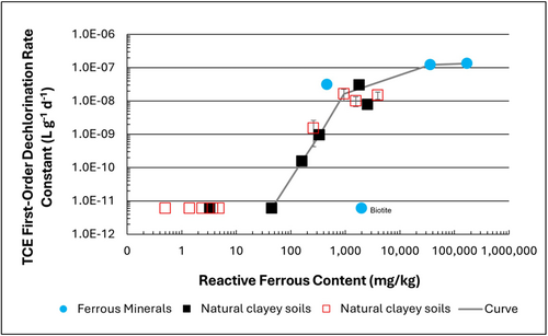
Figure 1: First-order rate constants for abiotic reductive dechlorination of TCE under anaerobic conditions. Circles are data from Schaefer
et al., 2021
[4], filled squares from Schaefer
et al., 2018
[5], and Schaefer
et al., 2017
[6], and open squares from Schaefer
et al., 2025
[1].
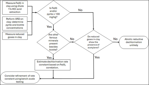
Figure 2: Flowchart diagram of field screening procedures
The recommended approach builds upon the methodology and findings of a recent study[1], emphasizing field-based and analytical techniques to quantify abiotic first-order reductive dechlorination rate constants for PCE and TCE in clayey soils under anoxic conditions. Key components of this evaluation are listed below:
- Zone Identification: The focus of the investigation should be to delineate clayey zones adjacent to hydraulically conductive zones.
- Ferrous Mineral Quantification: Assess ferrous mineral context in clay via 1% HCl extraction at ambient temperature over a 10-minute interval.
- Mineralogical Characterization: Conduct XRD analysis with the specific intent of identifying the presence of pyrite and biotite.
- Reduced Gas Analysis: Measurement of reduced gases such as acetylene, ethene, and ethane concentrations in clay samples. Gas-tight sampling devices (e.g., En Core® soil samplers by En Novative Technologies, Inc.) should be used to ensure sample integrity during collection and transport.
Clay samples should be collected within a few centimeters of the high-permeability interface, with optional additional sampling further inward. For mineralogical analysis, a defined interval may be collected and subsequently subsampled. To preserve sample integrity, exposure to air should be minimized during collection, transport, and handling. Homogenization should occur within an anaerobic chamber, and if subsamples are required for external analysis, they must be shipped in gas-tight, anaerobic containers.
Estimation of the abiotic reductive first-order rate constant for PCE and TCE is based on the “reactive” ferrous content in the clay. Reactive ferrous content (Fe(II)r) is estimated as shown in Equation 1:
- Equation 1: Fe(II)r = DA + XRDpyr - XRDbiotite
where DA is the ferrous content from the dilute acid (1% HCl) extraction, XRDpyr is the pyrite content from XRD analysis, and XRDbiotite is the biotite content from XRD analysis[1].
Abiotic dechlorination is unlikely to contribute to mitigating contaminant back-diffusion when reactive ferrous iron (Fe(II)r) concentrations are below 100 mg/kg (Figure 1). For Fe(II)r above 100 mg/kg, the first-order rate constant for PCE and TCE reductive dechlorination can be estimated using the correlation shown in Figure 1[5][7]. The rate constant exhibits a strong positive correlation with the logarithm of reactive Fe(II) content (Pearson’s r = 0.82), with a slope of 4.7 × 10⁻⁸ L g⁻¹ d⁻¹ (log mg kg⁻¹)⁻¹.
Figure 2 presents a decision flowchart designed to evaluate the significance and extent of abiotic reductive dechlorination. By applying Equation 1 to the dilute acid extractable Fe(II) plus measured mineral species data from clay samples, the reactive ferrous iron content (Fe(II)r) can be quantified, enabling a streamlined assessment of the extent to which abiotic processes are contributing to the mitigation of contaminant back-diffusion.
If Fe(II)r is ≥ 100 mg/kg, a first-order dechlorination rate constant can be estimated and subsequently used within a contaminant fate and transport model. However, if acetylene is detected in the clay, even with Fe(II)r less than 100 mg/kg, then bench-scale testing using methods similar to those described in a recent study[1] is recommended, as such results would likely be inconsistent with those shown in Figure 1, suggesting some other mechanism might be involved, or that the system mineralogy might be more complex than anticipated. Even if Fe(II)r ≥ 100 mg/kg, confirmatory bench-scale testing may be conducted for additional verification and to refine estimation of the abiotic dechlorination rate constant.
Summary and Recommendations
The approach outlined above is intended to serve as a generalized guide for practitioners and site managers to cost-effectively determine the extent to which beneficial abiotic reductive dechlorination reactions are likely occurring in low permeability (e.g., clayey) zones. This approach may be contraindicated if co-contaminants are present. It is currently unclear whether other classes of potentially reactive chemicals, such as trinitrotoluene (TNT) or chlorinated ethanes, could interact competitively with PCE and TCE.
In addition, it remains unclear how other classes of compounds such as per- and polyfluoroalkyl substances (PFAS) may interact or sorb with ferrous minerals and potentially inhibit abiotic dechlorination reactions. Coupling these recommended activities with conventional site investigation tasks would provide an opportunity to perform many of the up-front screening activities with minimal additional project costs. It is important to note that the guidance proposed herein pertains to particularly low permeability media. Sites with complex or varying lithology, where the mineralogy and/or redox conditions may vary, might require evaluation of multiple samples to provide appropriate site-wide information.
References
- ^ 1.0 1.1 1.2 1.3 1.4 Schaefer, C.E., Tran, D., Nguyen, D., Latta, D.E., Werth, C.J., 2025. Evaluating Mineral and In Situ Indicators of Abiotic Dechlorination in Clayey Soils. Groundwater Monitoring and Remediation, 45(2), pp. 31-39. doi: 10.1111/gwmr.12709
- ^ Falta, R., and Wang, W., 2017. A semi-analytical method for simulating matrix diffusion in numerical transport models. Journal of Contaminant Hydrology, 197, pp. 39-49. doi: 10.1016/j.jconhyd.2016.12.007 Open Access Manuscript
- ^ Kulkarni, P.R., Adamson, D.T., Popovic, J., Newell, C.J., 2022. Modeling a well-charactized perfluorooctane sulfate (PFOS) source and plume using the REMChlor-MD model to account for matrix diffusion. Journal of Contaminant Hydrology, 247, Article 103986. doi: 10.1016/j.jconhyd.2022.103986 Open Access Manuscript
- ^ Schaefer, C.E., Ho, P., Berns, E., Werth, C., 2021. Abiotic dechlorination in the presence of ferrous minerals. Journal of Contaminant Hydrology, 241, 103839. doi: 10.1016/j.jconhyd.2021.103839 Open Access Manuscript
- ^ 5.0 5.1 Schaefer, C.E., Ho, P., Berns, E., Werth, C., 2018. Mechanisms for abiotic dechlorination of trichloroethene by ferrous minerals under oxic and anoxic conditions in natural sediments. Environmental Science and Technology, 52(23), pp.13747-13755. doi: 10.1021/acs.est.8b04108
- ^ Schaefer, C.E., Ho., Gurr, C., Berns, E., Werth, C., 2017. Abiotic dechlorination of chlorinated ethenes in natural clayey soils: impacts of mineralogy and temperature. Journal of Contaminant Hydrology, 206, pp. 10-17. doi: 10.1016/j.jconhyd.2017.09.007 Open Access Manuscript
- ^ Borden, R.C., Cha, K.Y., 2021. Evaluating the impact of back diffusion on groundwater cleanup time. Journal of Contaminant Hydrology, 243, Article 103889. doi: 10.1016/j.jconhyd.2021 Open Access Manuscript
See Also

