|
|
| Line 1: |
Line 1: |
| − | The persistent release of residual contaminants from low hydraulic conductivity (low ''k'') zones prevents many chlorinated solvent sites from reaching groundwater cleanup goals. Low ''k'' aquifer settings limit the effectiveness of many conventional remediation technologies that rely on extraction, recirculation, or amendment delivery and distribution to achieve contact between the residual contaminants and the reagents, contact which is necessary for subsequent contaminant transformation or destruction. Alternative methods are needed to effectively distribute remedial amendments, to control contaminants leaving low ''k'' source zones, and to enhance natural attenuation processes. Two innovative remediation technologies for the treatment of chlorinated solvents and other contaminants in low ''k'' media are introduced, along with operational and performance results from recent field demonstrations. | + | ==Estimating PCE/TCE Abiotic First-Order Reductive Dechlorination Rate Constants in Clayey Soils Under Anoxic Conditions== |
| | + | The U.S. Department of Defense (DoD) faces many challenges in restoring aquifers at contaminated sites, often due to back-diffusion of tetrachloroethene (PCE) and trichloroethene (TCE) from low-permeability clay zones. The uptake, storage, and subsequent long-term release of these dissolved contaminants from clays are key processes in understanding the longevity, intensity, and risks associated with many persistent chlorinated ethene groundwater plumes. Although naturally occurring abiotic and biotic dechlorination processes in clays may reduce stored contaminant mass and significantly aid natural attenuation, no standardized field method currently exists to verify or quantify these reactions. It is critical to remediation design efforts to demonstrate and validate a cost-effective in situ approach for assessing these dechlorination processes using first-order rate constants. An approach was developed and applied across eight DoD sites to support Remedial Project Managers (RPMs) and regulators in evaluating natural attenuation potential in clay-rich environments. |
| | <div style="float:right;margin:0 0 2em 2em;">__TOC__</div> | | <div style="float:right;margin:0 0 2em 2em;">__TOC__</div> |
| | | | |
| | '''Related Article(s):''' | | '''Related Article(s):''' |
| − | * [[Bioremediation - Anaerobic | Anaerobic Bioremediation]]
| |
| − | * [[Chemical Oxidation (In Situ - ISCO) | In Situ Chemical Oxidation]]
| |
| − | * [[Chemical Reduction (In Situ - ISCR) | In Situ Chemical Reduction]]
| |
| | | | |
| − | '''CONTRIBUTOR(S): '''
| + | *[[Monitored Natural Attenuation (MNA)]] |
| − | * [[Stephen D. Richardson, Ph.D., PE]] | + | *[[Monitored Natural Attenuation (MNA) of Chlorinated Solvents]] |
| − | * [[Craig E. Divine, Ph.D., PG]] | + | *[[Monitored Natural Attenuation - Transitioning from Active Remedies]] |
| | + | *[[Matrix Diffusion]] |
| | + | *[[REMChlor - MD]] |
| | | | |
| − | '''Key Resource(s):''' | + | '''Contributors:''' Dani Tran, Dr. Charles Schaefer, Dr. Charles Werth |
| − | * The Horizontal Reactive Media Treatment Well (HRX Well<sup>®</sup>) for Passive In-Situ Remediation<ref name="Divine2018a">Divine, C. E., Roth, T, Crimi, M., DiMarco, A.C., Spurlin, M., Gillow, J., and Leone, G., 2018. The Horizontal Reactive Media Treatment Well (HRX Well<sup>®</sup>) for Passive In-Situ Remediation. Groundwater Monitoring & Remediation, 38(1), pp. 56–65. [https://doi.org/10.1111/gwmr.12252 DOI: 10.1111/gwmr.12252]</ref>
| |
| | | | |
| − | * The Horizontal Reactive Media Treatment Well (HRX Well<sup>®</sup>) for Passive In Situ Remediation: Design, Implementation, and Sustainability Considerations<ref name="Divine2018">Divine, C.E., Wright, J., Wang, J., McDonough, J., Kladias, M., Crimi, M., Nzeribe, B.N., Devlin, J.F., Lubrecht, M., Ombalski, D., Hodge, B., Voscott, H., and Gerber, K., 2018. The Horizontal Reactive Media Treatment Well (HRX Well<sup>®</sup>) for Passive In Situ Remediation: Design, Implementation, and Sustainability Considerations. Remediation, 28(4), pp. 5-16. [https://doi.org/10.1002/rem.21571 DOI: 10.1002/rem.21571] Also available from: [https://www.researchgate.net/publication/327487096_The_horizontal_reactive_media_treatment_well_HRX_WellR_for_passive_in_situ_remediation_Design_implementation_and_sustainability_considerations ResearchGate]</ref> | + | '''Key Resource:''' |
| − | | + | *Schaefer, C.E, Tran, D., Nguyen, D., Latta, D.E., Werth, C.J., 2025. Evaluating Mineral and In Situ Indicators of Abiotic Dechlorination in Clayey Soils<ref name="SchaeferEtAl2025"/> |
| − | * New Application of A Geotechnical Technology to Remediate Low-Permeability Contaminated Media – Final Technical Report<ref name="Richardson2020">Richardson, S.D., Hart, D.M., Long, J.A., and Newell, C.J., 2020. New Application of A Geotechnical Technology to Remediate Low-Permeability Contaminated Media – Final Technical Report. ER-201627, Environmental Security Technology Certification Program (ESTCP). [https://www.serdp-estcp.org/Program-Areas/Environmental-Restoration/Contaminated-Groundwater/Persistent-Contamination/ER-201627/ Project Overview]</ref>
| |
| | | | |
| | ==Introduction== | | ==Introduction== |
| − | [[File:Richardson1w2Fig1.png | thumb | 400px | Figure 1. Examples of low ''k'' geology. Upper left: bay muds, Oakland, California; lower left: weathered siltstone, Denver, Colorado; right: tailings slimes, central New Mexico<ref name="Horst2019"/>.]]
| + | Cost-effective methods are needed to verify the occurrence of natural dechlorination processes and quantify their dechlorination rates in clays under ambient in situ conditions in order to reliably predict their long-term influence on plume longevity and mass discharge. However, accurately determining these rates is challenging due to slow reaction kinetics, the transient nature of transformation products, and the interplay of biotic and abiotic mechanisms within the clay matrix or at clay-sand interfaces. Tools capable of quantifying these reactions and assessing their role in mitigating plume persistence would be a significant aid for long-term site management. |
| − | [[File:Richardson1w2Fig2.png | thumb | 400px | Figure 2. Contaminant back diffusion (“Matrix Diffusion”) from low ''k'' zones<ref name="NRC2005">National Research Council, 2005. Contaminants in the Subsurface: Source Zone Assessment and Remediation. National Academies Press, Washington, DC, pp. 372. [https://doi.org/10.17226/11146 DOI: 10.17226/11146] [[Media: NRC2005.pdf | Book.pdf]]</ref>.]]
| |
| − | A critical challenge preventing many chlorinated solvent sites from achieving groundwater cleanup goals is the long term release of residual contaminants from low hydraulic conductivity (low ''k'') zones such as silts, clays, glacial till, over-bank deposits, marine deposits, tailings “slimes”, saprolite and bedrock (see Figure 1)<ref name ="Horst2019">Horst, J., Divine, C., Schnobrich, M., Oesterreich, R., and Munholland, J., 2019. Groundwater Remediation in Low-Permeability Settings: The Evolving Spectrum of Proven and Potential. Groundwater Monitoring & Remediation, 39(1), pp. 11-19. [https://doi.org/10.1111/gwmr.12316 DOI: 10.1111/gwmr.12316]</ref><ref name ="Sale2008">Sale, T., C. Newell, H. Stroo, R. Hinchee, and Johnson, P., 2008. Frequently Asked Questions Regarding Management of Chlorinated Solvents in Soils and Groundwater. Environmental Security Technology Certification Program (ESTCP) Project ER-0530, 38 pp. [[Media:2008-Sale-Frequently_Asked_Questions_Regarding_Management_of_Chlorinated_Solvent_in_Soils_and_Groundwater.pdf | Report.pdf]] [https://serdp-estcp.org/Program-Areas/Environmental-Restoration/Contaminated-Groundwater/Persistent-Contamination/ER-200530/(language)/eng-US Project overview]</ref>. Such sites may be dominated by matrix diffusion processes (see Figure 2) which can significantly prolong restoration and site management timeframes. Residual contaminants residing in low permeability zones slowly diffuse from the low ''k'' matrix back into higher permeability zones, becoming a persistent source that is very difficult to remediate. One of the side effects of matrix diffusion is concentration rebound after an ''in situ'' treatment is applied. This is commonly observed at sites treated with chemical oxidation<ref name="McGuire2006">McGuire, T.M., McDade, J.M., and Newell, C.J., 2006. Performance of DNAPL Source Depletion Technologies at 59 Chlorinated Solvent-Impacted Sites. Groundwater Monitoring & Remediation. Volume 26, Issue 1, pp. 73-84. [https://doi.org/10.1111/j.1745-6592.2006.00054.x DOI: 10.1111/j.1745-6592.2006.00054.x] [https://www.provectusenvironmental.com/marketing/p-ox1/McGuire%20et%20al%202006.pdf Free download.pdf]</ref><ref name="Krembs2010">Krembs, F., Siegrist, R., Crimi, M., Furrer, R., and Petri, B., 2010. ISCO for Groundwater Remediation: Analysis of Field Applications and Performance. Groundwater Monitoring & Remediation, 30(4), pp. 42-53. [https://doi.org/10.1111/j.1745-6592.2010.01312.x DOI: 10.1111/j.1745-6592.2010.01312.x]</ref> and has the potential to occur at ''in situ'' bioremediation sites after the depletion of electron donors<ref name="Adamson2011">Adamson, D., McGuire, T., Newell, C., and Stroo, H., 2011. Sustained Treatment: Implications for Treatment Timescales Associated with Source-Depletion Technologies. Remediation, 21(2), pp. 27-50. [https://doi.org/10.1002/rem.20280 DOI: 10.1002/rem.20280]</ref>.
| |
| − | | |
| − | Currently, there are limited remediation options available to treat residual contamination trapped in low ''k'' zones. Low ''k'' settings limit the applicability and effectiveness of conventional remediation technologies due to the constraint on fluid introduction and recovery. As such, methods relying on extraction, recirculation, or reagent delivery and distribution are often limited in their effectiveness. For the long lived, difficult to treat sites, innovative technologies are needed that will reliably address mass flux limitations of contaminants leaving low ''k'' source zones, and also increase the actual treatment of the contaminants leaving these low ''k'' zones by enhancing natural attenuation processes. Two innovative technologies investigated by ESTCP are summarized below.
| |
| − | | |
| − | ==“Grout Bomber”==
| |
| − | ===Technology Description===
| |
| − | [[File:Richardson1w2Fig3.png | thumb | left | 400px | Figure 3. a) Grout Bomber equipment; b) hopper for mixing and delivery of grout to the “stitcher”; and c) grout exiting the mandrel]]
| |
| − | [[File:Richardson1w2Fig4.png | thumb | left | 400px | Figure 4. Application of the Bomber technology for contaminated sites in low ''k'' materials.]]
| |
| − | [[File:Richardson1w2Fig5.png | thumb | left | 400px | Figure 5. Chlorinated ethene concentrations at well pair (CMT-1 and IS17MW04).]]
| |
| − | The geotechnical industry offers a variety of well-established techniques for quickly and efficiently accessing the subsurface for the purposes of ground stabilization, foundation rehabilitation, porewater drainage, and structural support. The speed and efficiency of these techniques can also be a major advantage for emplacement of remedial amendments into the subsurface. One promising approach is the Grout Bomber, a larger adaptation of conventional cement or compaction grouting techniques for subsurface stabilization. The technology uses an excavator equipped with specialized equipment (a “stitcher”) to quickly push a mandrel (3.5 in. diameter hollow cylindrical rod) into the subsurface and subsequently fill the hole and subsurface voids with cement grout (from bottom to top) using an in-line grout delivery system. The typical arrangement of the Grout Bomber technology includes the installation rig (excavator with the “stitcher” mast; see Figure 3a) and an on-site grout mixing and delivery unit consisting of mixing hopper, pumps, hosing, and power supply. Raw materials are loaded into the mixing hopper (see Figure 3b) where it is mixed to the appropriate consistency, then pumped to the Bomber rig at a rate of approximately 0.25 cubic feet per pump stroke. At the exit end of the Bomber mandrel (see Figure 3c), the grout flows in a continuous and uniform manner, allowing the columns to be emplaced with grout while the mandrel (which was pushed into the subsurface) is lifted to the surface. Hundreds of closely spaced vertical grout columns can be installed per day using this technology.
| |
| | | | |
| − | For environmental applications, the Grout Bomber approach can be “repurposed” as a means to improve delivery of remediation amendments into contaminated treatment zones in low ''k'' materials. The remedial amendment (e.g., mixture of zero-valent iron (ZVI), sand, neat oil) can replace the grout and be directly placed into the subsurface from bottom to top (not injected into the surrounding formation), creating hundreds of reaction columns. The Bomber technology offers the following benefits: | + | For reductive abiotic dechlorination under anoxic conditions, a 1% hydrochloric acid (HCl) extraction of a sample of native clay coupled with X-ray diffraction (XRD) data can be used as a screening level tool to estimate reductive dechlorination rate constants. These rate constants can be inserted into fate and transport models such as [[REMChlor - MD]]<ref>Falta, R., and Wang, W., 2017. A semi-analytical method for simulating matrix diffusion in numerical transport models. Journal of Contaminant Hydrology, 197, pp. 39-49. [https://doi.org/10.1016/j.jconhyd.2016.12.007 doi: 10.1016/j.jconhyd.2016.12.007] [[Media: FaltaWang2017.pdf | Open Access Manuscript]]</ref><ref>Kulkarni, P.R., Adamson, D.T., Popovic, J., Newell, C.J., 2022. Modeling a well-charactized perfluorooctane sulfate (PFOS) source and plume using the REMChlor-MD model to account for matrix diffusion. Journal of Contaminant Hydrology, 247, Article 103986. [https://doi.org/10.1016/j.jconhyd.2022.103986 doi: 10.1016/j.jconhyd.2022.103986] [[Media: KulkarniEtAl2022.pdf | Open Access Manuscript]]</ref> to quantify abiotic dechlorination impacts within clay aquitards on chlorinated solvent plumes. Thus, determination of the abiotic reductive dechlorination rate constant for a particular clayey soil can be readily utilized to provide a more accurate assessment of aquifer cleanup timeframes for groundwater plumes that are being sustained by contaminant back-diffusion. |
| − | * '''Reduces uncertainty: '''
| |
| − | The Bomber technology circumvents the “delivery problem” associated with conventional injection-based remediation approaches, particularly in low ''k'' zones. The closely spaced nature of the reaction columns (2-3 ft spacing) reduces the diffusion lengths out of low ''k'' zones and also the uncertainty associated with amendment delivery because contaminants are always < 1 - 1.5 ft from an active treatment zone (see Figure 4).
| |
| | | | |
| − | * '''Rapid installation of reaction columns: '''
| + | ==Recommended Approach== |
| − | The Grout Bomber can install 100+ reaction columns per day to depths of 40-50 ft below ground surface (bgs) to encourage contaminant degradation in source zones. Since the Grout Bomber is a direct push technique, it is better suited to silts and clays with blow counts < 35. Consolidated materials with higher blow counts will require additional equipment to pre-drill the columns prior to amendment emplacement. In general, this technology represents a much simpler, less intensive, and easier to install version of complete soil mixing. | + | [[File: TranFig1.png | thumb | 500 px | Figure 1: First-order rate constants for abiotic reductive dechlorination of TCE under anaerobic conditions. Circles are data from Schaefer ''et al.'', 2021<ref>Schaefer, C.E., Ho, P., Berns, E., Werth, C., 2021. Abiotic dechlorination in the presence of ferrous minerals. Journal of Contaminant Hydrology, 241, 103839. [https://doi.org/10.1016/j.jconhyd.2021.103839 doi: 10.1016/j.jconhyd.2021.103839] [[Media: SchaeferEtAl2021.pdf | Open Access Manuscript]]</ref>, filled squares from Schaefer ''et al.'', 2018<ref name="SchaeferEtAl2018"/>, and Schaefer ''et al.'', 2017<ref>Schaefer, C.E., Ho., Gurr, C., Berns, E., Werth, C., 2017. Abiotic dechlorination of chlorinated ethenes in natural clayey soils: impacts of mineralogy and temperature. Journal of Contaminant Hydrology, 206, pp. 10-17. [https://doi.org/10.1016/j.jconhyd.2017.09.007 doi: 10.1016/j.jconhyd.2017.09.007] [[Media: SchaeferEtAl2017.pdf | Open Access Manuscript]]</ref>, and open squares from Schaefer ''et al.'', 2025<ref name="SchaeferEtAl2025"/>. ]] |
| | + | [[File: TranFig2.png | thumb | 600 px | Figure 2: Flowchart diagram of field screening procedures]] |
| | + | The recommended approach builds upon the methodology and findings of a recent study<ref name="SchaeferEtAl2025">Schaefer, C.E., Tran, D., Nguyen, D., Latta, D.E., Werth, C.J., 2025. Evaluating Mineral and In Situ Indicators of Abiotic Dechlorination in Clayey Soils. Groundwater Monitoring and Remediation, 45(2), pp. 31-39. [https://doi.org/10.1111/gwmr.12709 doi: 10.1111/gwmr.12709]</ref>, emphasizing field-based and analytical techniques to quantify abiotic first-order reductive dechlorination rate constants for PCE and TCE in clayey soils under anoxic conditions. Key components of this evaluation are listed below: |
| | + | #<u>Zone Identification:</u> The focus of the investigation should be to delineate clayey zones adjacent to hydraulically conductive zones. |
| | + | #<u>Ferrous Mineral Quantification:</u> Assess ferrous mineral context in clay via 1% HCl extraction at ambient temperature over a 10-minute interval. |
| | + | #<u>Mineralogical Characterization:</u> Conduct XRD analysis with the specific intent of identifying the presence of pyrite and biotite. |
| | + | #<u>Reduced Gas Analysis:</u> Measurement of reduced gases such as acetylene, ethene, and ethane concentrations in clay samples. Gas-tight sampling devices (e.g., En Core® soil samplers by En Novative Technologies, Inc.) should be used to ensure sample integrity during collection and transport. |
| | | | |
| − | * '''Accommodates various amendment types: '''
| + | Clay samples should be collected within a few centimeters of the high-permeability interface, with optional additional sampling further inward. For mineralogical analysis, a defined interval may be collected and subsequently subsampled. To preserve sample integrity, exposure to air should be minimized during collection, transport, and handling. Homogenization should occur within an anaerobic chamber, and if subsamples are required for external analysis, they must be shipped in gas-tight, anaerobic containers. |
| − | In one example<ref name="Richardson2020"/>, vertical reaction columns containing a mixture of ZVI, vegetable oil, sand and minor amounts of water were installed to a depth of 30 ft bgs in a low ''k'' treatment area consisting primarily of silts, sandy clays, and lean clays<ref name="Divine2018"/>. The ZVI-sand-oil mixture was designed to have a similar consistency (or viscosity) to cement grout, thus requiring no major alterations to the existing Bomber equipment for the project. Recommended practices to ensure uninterrupted flow of amendments to the Bomber mandrel include:
| |
| − | ** Conduct simple pumping pilot studies with amendments of varying consistencies,
| |
| − | ** Consult with a well trained pump operator, and
| |
| − | ** Minimize the length of hosing between mixing hopper pump and Bomber mandrel.
| |
| | | | |
| − | * '''Cost effective source zone treatment: '''
| + | Estimation of the abiotic reductive first-order rate constant for PCE and TCE is based on the “reactive” ferrous content in the clay. Reactive ferrous content (Fe(II)<sub>r</sub>) is estimated as shown in Equation 1: |
| − | Estimated treatment costs associated with emplacement of amendments with the Grout Bomber are ~$35 per cubic yard of source zone treated (including contractor labor, equipment, and materials). This is generally less than the reported unit cost for ''in situ'' biodegradation ($20-$80/yd<sup>3</sup>) and significantly less than chemical oxidation ($125/yd<sup>3</sup>) and thermal remediation (median $200/yd<sup>3</sup>)<ref name="McDade2005">McDade, J.M., T.M. McGuire, and Newell, C.J., 2005. Analysis of DNAPL Source Depletion Costs at 36 Field Sites, Remediation, 15(2), pp. 9-18. [https://doi.org/10.1002/rem.20039 DOI: 10.1002/rem.20039]</ref>.
| |
| | | | |
| − | ===Operational Approach & Results===
| + | ::'''Equation 1:''' <big>''Fe(II)<sub><small>r</small></sub> = DA + XRD<sub><small>pyr</small></sub> - XRD<sub><small>biotite</small></sub>''</big> |
| − | A field demonstration was conducted at Site 17, Naval Support Facility Indian Head, Maryland. The treatment area consists primarily of silts, sandy clays, and lean clays with TCE concentrations in soil and groundwater of up to 250 mg/kg and 400 mg/L, respectively. Eight hundred reaction columns (consisting of ZVI/sand or oil/sand), were installed 2-3 ft apart, to a depth of 30 ft bgs at the site. Approximately 100 reaction columns were installed per day, with the most productive day totaling 180 columns. During operation, installation time for each reaction column was on the order of 1-2 minutes. Overall, 77,000 lbs of ZVI and 650 gallons of vegetable oil were emplaced within the source area of ~5,000 ft<sup>2</sup>.
| |
| | | | |
| − | ===Performance Results===
| + | where ''DA'' is the ferrous content from the dilute acid (1% HCl) extraction, ''XRD<sub><small>pyr</small></sub>'' is the pyrite content from XRD analysis, and ''XRD<sub><small>biotite</small></sub>'' is the biotite content from XRD analysis<ref name="SchaeferEtAl2025"/>. |
| − | Ongoing post installation monitoring of treatment area groundwater has found moderate reductions in TCE in site monitoring wells and that key degradation products that serve as indicators for both abiotic and biotic mechanisms (i.e., acetylene, ethene/ethane) are present. Samples from Continuous Multilevel Tubing (CMT) wells installed within reaction columns (anulus filled with ZVI amendment) have demonstrated 1-3 orders of magnitude reductions in TCE relative to the surrounding formation water (see Figure 5). These results provide evidence that the reaction columns are creating steep concentration gradients that could drive contaminants out of low permeability zones. Further, gaseous products (e.g., propane, propene, i-butane, n-butane, n-pentane, n-hexane) were detected in the unsaturated zone of several reaction columns further supporting abiotic TCE degradation. Results of this full scale project were very promising and, although several operational improvements were identified (e.g., improved pumpability of ZVI/sand mixture; minor equipment modifications; improved site prep practices), the Bomber technology has the potential to be an important remediation alternative for hard-to-treat chlorinated source zones, particularly ones with large, persistent matrix diffusion sources over large areas.
| |
| | | | |
| − | ==Horizontal Reactive Treatment Well (HRX Well<sup><small>®</small></sup>)==
| + | Abiotic dechlorination is unlikely to contribute to mitigating contaminant back-diffusion when reactive ferrous iron (Fe(II)<sub><small>r</small></sub>) concentrations are below 100 mg/kg (Figure 1). For Fe(II)<sub><small>r</small></sub> above 100 mg/kg, the first-order rate constant for PCE and TCE reductive dechlorination can be estimated using the correlation shown in Figure 1<ref name="SchaeferEtAl2018">Schaefer, C.E., Ho, P., Berns, E., Werth, C., 2018. Mechanisms for abiotic dechlorination of trichloroethene by ferrous minerals under oxic and anoxic conditions in natural sediments. Environmental Science and Technology, 52(23), pp.13747-13755. [https://doi.org/10.1021/acs.est.8b04108 doi: 10.1021/acs.est.8b04108]</ref><ref>Borden, R.C., Cha, K.Y., 2021. Evaluating the impact of back diffusion on groundwater cleanup time. Journal of Contaminant Hydrology, 243, Article 103889. [https://doi.org/10.1016/j.jconhyd.2021.103889 doi: 10.1016/j.jconhyd.2021] [[Media: BordenCha2021.pdf | Open Access Manuscript]]</ref>. The rate constant exhibits a strong positive correlation with the logarithm of reactive Fe(II) content (Pearson’s ''r'' = 0.82), with a slope of 4.7 × 10⁻⁸ L g⁻¹ d⁻¹ (log mg kg⁻¹)⁻¹. |
| − | {| class="wikitable" style="margin-left: auto; margin-right: 30px; float:left; text-align:center;"
| |
| − | |+ Table 1. Potential reactive media types and target groundwater contaminants for an HRX Well<sup>®</sup>
| |
| − | |-
| |
| − | ! Reactive Media !! Potential Target Groundwater Contaminants
| |
| − | |-
| |
| − | | Zero valent iron (ZVI)</br>Bimetallics (e.g., ZVI + Pd, Pt, or Ni) || Chlorinated solvents (CVOCs), nitrate, perchlorate, energetics, chromium, arsenic
| |
| − | |-
| |
| − | | Granulated activated carbon (GAC)</br>Organosilicates || CVOCs, Poly- and Perfluoroalkyl substances (PFASs), hydrocarbons, halomethanes
| |
| − | |-
| |
| − | | Sustained Release Oxidants || CVOCs, 1,4-dioxane, hydrocarbons,</br>polyaromatic hydrocarbons (PAHs), phenolic compounds
| |
| − | |-
| |
| − | | Biodegradable particulate organic carbon</br>(e.g., mulch) || CVOCs, nitrate, perchlorate, energetics
| |
| − | |-
| |
| − | | Ion exchange resins || PFAS, brines
| |
| − | |-
| |
| − | | Phosphates (e.g., apatite) || Lead, uranium, other metals and radionuclides
| |
| − | |-
| |
| − | | Limestone, lime, magnesium oxide || Low pH, acid rock drainage
| |
| − | |-
| |
| − | | Barium sulfate (barite) || Radium
| |
| − | |-
| |
| − | | Iron sulfide || Chromium, high pH
| |
| − | |-
| |
| − | | Zeolites || Ammonium, radionuclides, PFAS
| |
| − | |}
| |
| − | [[File:Richardson1w2Fig6.png | thumb | 400px | Figure 6. Conceptual HRX Well design<ref name="Divine2018a"/>. Groundwater (blue flowlines) is passively focused and flows into the fully screened HRX Well where it is treated as it flows through reactive media before exiting back into the aquifer. The hot colors represent high contaminant concentrations and cool colors represent treated water.]] | |
| − | [[File:Richardson1w2Fig7.png | thumb | 400px | Figure 7. HRX Well completion demonstrating the minimal surface footprint requirement.]] | |
| | | | |
| | + | Figure 2 presents a decision flowchart designed to evaluate the significance and extent of abiotic reductive dechlorination. By applying Equation 1 to the dilute acid extractable Fe(II) plus measured mineral species data from clay samples, the reactive ferrous iron content (Fe(II)<sub><small>r</small></sub>) can be quantified, enabling a streamlined assessment of the extent to which abiotic processes are contributing to the mitigation of contaminant back-diffusion. |
| | | | |
| − | The Horizontal Reactive Media Treatment Well (HRX Well<sup>®</sup>)<ref name="Divine2013"> Divine, C.E., Leone, G., Gillow, J, Roth, T., Brenton, H., and Spurlin, M., 2013. Horizontal In-well Treatment System and Source Area Bypass System and Method for Groundwater Remediation. U.S. Patent US8596351 B2. U.S. Patents and Trademarks Office, Alexandria, VA. [[Media: HRXwellPatent.pdf Patent.pdf ]]</ref><ref name="Divine2018a"/><ref name="Divine2018"/> is a new passive flux-control technology that utilizes large diameter horizontal wells filled with solid phase reactive media to treat contaminated groundwater ''in situ''. The HRX Well is installed parallel to the direction of groundwater flow and the design leverages natural “flow focusing” behavior induced by the engineered contrast in hydraulic conductivity between the reactive media and the ambient aquifer hydraulic conductivity to passively capture and treat proportionally large volumes of groundwater within the well. Treated groundwater then exits the horizontal well along its down-gradient sections (Figure 6). The HRX Well can quickly reduce contaminant mass flux and control migration, however it will not directly treat source mass or contamination located in low permeability zones. It requires a limited above-ground footprint (Figure 7) and can be installed under buildings or other surface infrastructure. In involves no active groundwater management or above ground treatment systems, and minimal ongoing maintenance (except for periodic media replacement as the media becomes exhausted). As shown in Table 1, many different types of solid reactive media are already available; therefore, this concept could be used to address a wide range of contaminants. Note that it is anticipated that solid phase media would be used in most applications, however, other media types or treatment processes could conceivably be employed. It is expected that reactive media use would be more efficient, and its eventual replacement would be simpler and less costly for an HRX Well than for a conventional [[Zerovalent Iron Permeable Reactive Barriers | Permeable Reactive Barrier (PRB)]].
| + | If Fe(II)r is ≥ 100 mg/kg, a first-order dechlorination rate constant can be estimated and subsequently used within a contaminant fate and transport model. However, if acetylene is detected in the clay, even with Fe(II)r less than 100 mg/kg, then bench-scale testing using methods similar to those described in a recent study<ref name="SchaeferEtAl2025"/> is recommended, as such results would likely be inconsistent with those shown in Figure 1, suggesting some other mechanism might be involved, or that the system mineralogy might be more complex than anticipated. Even if Fe(II)r ≥ 100 mg/kg, confirmatory bench-scale testing may be conducted for additional verification and to refine estimation of the abiotic dechlorination rate constant. |
| | | | |
| − | For relatively thin aquifers, the vertically averaged capture and treatment zone width (''w<sub><small>ave</small></sub>'') for an individual well can be estimated through a simple manipulation of Darcy’s Law<ref name="Divine2018a"/>:
| + | ==Summary and Recommendations== |
| − | ::{|
| + | The approach outlined above is intended to serve as a generalized guide for practitioners and site managers to cost-effectively determine the extent to which beneficial abiotic reductive dechlorination reactions are likely occurring in low permeability (e.g., clayey) zones. This approach may be contraindicated if co-contaminants are present. It is currently unclear whether other classes of potentially reactive chemicals, such as trinitrotoluene (TNT) or chlorinated ethanes, could interact competitively with PCE and TCE. |
| − | | Equation 1. ||'''''<big>w'''<sub><small>ave</small></sub>''' = <sup>(K<sub><small>HRX</small></sub> π r<sub><small>HRX</small></sub><sup>2</sup> i<sub><small>HRX</small></sub>)</sup> ⁄ <sub>(K<sub><small>A</small></sub> b<sub><small>A</small></sub> i<sub><small>A</small></sub>)</sub></big>'''''
| |
| − | |-
| |
| − | | Where:
| |
| − | |-
| |
| − | | ''K<sub><small>HRX</small></sub>'' || is the hydraulic conductivity of the treatment media,
| |
| − | |-
| |
| − | | ''r<sub><small>HRX</small></sub>'' || is the radius of the HRX Well,
| |
| − | |-
| |
| − | | ''i<sub><small>HRX</small></sub>'' || is the hydraulic gradient along the HRX Well,
| |
| − | |-
| |
| − | | ''K<sub><small>A</small></sub>'' || is the average hydraulic conductivity of the aquifer,
| |
| − | |-
| |
| − | | ''b<sub><small>A</small></sub>'' || is the targeted aquifer zone thickness, and
| |
| − | |-
| |
| − | | ''i<sub><small>A</small></sub>'' || is the ambient aquifer hydraulic gradient.
| |
| − | |}
| |
| − | In all cases, ''i<sub><small>HRX</small></sub>'' < ''i<sub><small>A</small></sub>'', but for short wells, ''i<sub><small>HRX</small></sub>'' << ''i<sub><small>A</small></sub>'', and ''w<sub><small>ave</small></sub>'' is small. However, for long wells (several hundred feet or more), the difference between the hydraulic gradients diminishes. When used as a screening calculation, ''i<sub><small>HRX</small></sub>'' and ''i<sub><small>A</small></sub>'' can be assumed to be approximately equal in many cases. By inspection of Equation 1, it is clear that ''w<sub><small>ave</small></sub>'' increases as the permeability contrast between the aquifer and reactive media increases, and therefore this approach may be practical and cost effective for many moderate and lower permeability sites. If necessary, multiple HRX Wells can be installed side by side to achieve target treatment widths.
| |
| | | | |
| − | {| style="float:left; margin-left:auto; margin-right:30px;
| + | In addition, it remains unclear how other classes of compounds such as per- and polyfluoroalkyl substances (PFAS) may interact or sorb with ferrous minerals and potentially inhibit abiotic dechlorination reactions. Coupling these recommended activities with conventional site investigation tasks would provide an opportunity to perform many of the up-front screening activities with minimal additional project costs. It is important to note that the guidance proposed herein pertains to particularly low permeability media. Sites with complex or varying lithology, where the mineralogy and/or redox conditions may vary, might require evaluation of multiple samples to provide appropriate site-wide information. |
| − | | [[File:Richardson1w2Fig8.png | thumb | 480px | Figure 8. Changes in groundwater flow characteristics before and after HRX Well installation showing the hydraulic effects of water discharging from the outlet screen. Posted and contoured values are groundwater elevations in feet above mean sea level.]]
| |
| − | | [[File:Richardson1w2Fig9.png | thumb | 400px | Figure 9. HRX Well installed at VAFB showing groundwater inflow (blue curved lines) and approximate outlet zone (shaded blue cone). Posted values represent reductions in TCE concentrations observed 436 days after HRX Well installation.]]
| |
| − | |}
| |
| − | The HRX Well concept has been evaluated with numerical models and physical sand tank experiments<ref name="Divine2018a"/><ref name="Divine2018"/>, and the first field scale installation of this technology was completed in August 2018 at Vandenberg Air Force Base (VAFB) in Central California. This purpose of the HRX Well is to control trichloroethene (TCE) flux in a thin (7 to 12 ft) low permeability aquifer (average hydraulic conductivity is approximately 0.1 to 0.5 ft/day) impacted at concentrations up to about 30 to 50 milligrams per liter (mg/L). The HRX Well consists of 85 ft of inlet screen and 70 ft of outlet screen separated by 165 ft of casing, with removeable treatment media cartridges (35 percent ZVI by weight, media hydraulic conductivity is approximately 100 ft/d) installed in 70 ft of the cased section. Hydraulic performance data (as shown in Figure 8) and treatment effectiveness data (Figure 9) indicate the following:
| |
| − | * The capture and treatment zone for this single HRX Well exceeded 50 ft, consistent with estimates predicted by Equation 1.
| |
| − | * TCE concentrations were reduced by more than 99.99% based on concentrations at the HRX Well outlet.
| |
| − | * Initial treatment response was observed in nearby monitoring wells generally within 150 days after HRX Well installation, which is consistent with the design model.
| |
| − | * 436 days after HRX Well installation, the TCE concentration in treatment wells was reduced by an average of 63%.
| |
| | | | |
| − | For this site, the HRX Well concept compared favorably in terms of sustainability, relative to pump and treat (P&T) and conventional trench based PRB approaches. The system operates passively ''in situ'', therefore, the recurring and cumulative energy requirements, carbon footprint, life cycle water consumption, recurring material use, and waste generation are low, and are primarily associated with replacement of treatment media. For the VAFB site, ZVI is contained in removable cartridges that are anticipated to require replacement every five to 10 years. However, media replacement frequency is site specific and a function of contaminant loading and treatment media volume and characteristics. Lifecycle cost estimates for full-scale 30-yr systems also compared favorably: $2.5M to $3.1M for a three well HRX Well system, $3.8M to $4.7M for a P&T system, and $3.6M to $4.5M for a PRB design.
| + | <br clear="right"/> |
| | | | |
| | ==References== | | ==References== |
| − | | + | <references /> |
| − | <references/> | |
| | | | |
| | ==See Also== | | ==See Also== |
| | + | *[https://serdp-estcp.mil/projects/details/a7e3f7b5-ed82-4591-adaa-6196ff33dd60 ESTCP Project ER20-5031 – In Situ Verification and Quantification of Naturally Occurring Dechlorination Rates in Clays: Demonstrating Processes that Mitigate Back-Diffusion and Plume Persistence] |
Estimating PCE/TCE Abiotic First-Order Reductive Dechlorination Rate Constants in Clayey Soils Under Anoxic Conditions
The U.S. Department of Defense (DoD) faces many challenges in restoring aquifers at contaminated sites, often due to back-diffusion of tetrachloroethene (PCE) and trichloroethene (TCE) from low-permeability clay zones. The uptake, storage, and subsequent long-term release of these dissolved contaminants from clays are key processes in understanding the longevity, intensity, and risks associated with many persistent chlorinated ethene groundwater plumes. Although naturally occurring abiotic and biotic dechlorination processes in clays may reduce stored contaminant mass and significantly aid natural attenuation, no standardized field method currently exists to verify or quantify these reactions. It is critical to remediation design efforts to demonstrate and validate a cost-effective in situ approach for assessing these dechlorination processes using first-order rate constants. An approach was developed and applied across eight DoD sites to support Remedial Project Managers (RPMs) and regulators in evaluating natural attenuation potential in clay-rich environments.
Related Article(s):
Contributors: Dani Tran, Dr. Charles Schaefer, Dr. Charles Werth
Key Resource:
- Schaefer, C.E, Tran, D., Nguyen, D., Latta, D.E., Werth, C.J., 2025. Evaluating Mineral and In Situ Indicators of Abiotic Dechlorination in Clayey Soils[1]
Introduction
Cost-effective methods are needed to verify the occurrence of natural dechlorination processes and quantify their dechlorination rates in clays under ambient in situ conditions in order to reliably predict their long-term influence on plume longevity and mass discharge. However, accurately determining these rates is challenging due to slow reaction kinetics, the transient nature of transformation products, and the interplay of biotic and abiotic mechanisms within the clay matrix or at clay-sand interfaces. Tools capable of quantifying these reactions and assessing their role in mitigating plume persistence would be a significant aid for long-term site management.
For reductive abiotic dechlorination under anoxic conditions, a 1% hydrochloric acid (HCl) extraction of a sample of native clay coupled with X-ray diffraction (XRD) data can be used as a screening level tool to estimate reductive dechlorination rate constants. These rate constants can be inserted into fate and transport models such as REMChlor - MD[2][3] to quantify abiotic dechlorination impacts within clay aquitards on chlorinated solvent plumes. Thus, determination of the abiotic reductive dechlorination rate constant for a particular clayey soil can be readily utilized to provide a more accurate assessment of aquifer cleanup timeframes for groundwater plumes that are being sustained by contaminant back-diffusion.
Recommended Approach
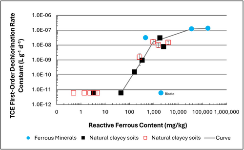
Figure 1: First-order rate constants for abiotic reductive dechlorination of TCE under anaerobic conditions. Circles are data from Schaefer
et al., 2021
[4], filled squares from Schaefer
et al., 2018
[5], and Schaefer
et al., 2017
[6], and open squares from Schaefer
et al., 2025
[1].
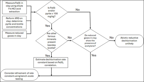
Figure 2: Flowchart diagram of field screening procedures
The recommended approach builds upon the methodology and findings of a recent study[1], emphasizing field-based and analytical techniques to quantify abiotic first-order reductive dechlorination rate constants for PCE and TCE in clayey soils under anoxic conditions. Key components of this evaluation are listed below:
- Zone Identification: The focus of the investigation should be to delineate clayey zones adjacent to hydraulically conductive zones.
- Ferrous Mineral Quantification: Assess ferrous mineral context in clay via 1% HCl extraction at ambient temperature over a 10-minute interval.
- Mineralogical Characterization: Conduct XRD analysis with the specific intent of identifying the presence of pyrite and biotite.
- Reduced Gas Analysis: Measurement of reduced gases such as acetylene, ethene, and ethane concentrations in clay samples. Gas-tight sampling devices (e.g., En Core® soil samplers by En Novative Technologies, Inc.) should be used to ensure sample integrity during collection and transport.
Clay samples should be collected within a few centimeters of the high-permeability interface, with optional additional sampling further inward. For mineralogical analysis, a defined interval may be collected and subsequently subsampled. To preserve sample integrity, exposure to air should be minimized during collection, transport, and handling. Homogenization should occur within an anaerobic chamber, and if subsamples are required for external analysis, they must be shipped in gas-tight, anaerobic containers.
Estimation of the abiotic reductive first-order rate constant for PCE and TCE is based on the “reactive” ferrous content in the clay. Reactive ferrous content (Fe(II)r) is estimated as shown in Equation 1:
- Equation 1: Fe(II)r = DA + XRDpyr - XRDbiotite
where DA is the ferrous content from the dilute acid (1% HCl) extraction, XRDpyr is the pyrite content from XRD analysis, and XRDbiotite is the biotite content from XRD analysis[1].
Abiotic dechlorination is unlikely to contribute to mitigating contaminant back-diffusion when reactive ferrous iron (Fe(II)r) concentrations are below 100 mg/kg (Figure 1). For Fe(II)r above 100 mg/kg, the first-order rate constant for PCE and TCE reductive dechlorination can be estimated using the correlation shown in Figure 1[5][7]. The rate constant exhibits a strong positive correlation with the logarithm of reactive Fe(II) content (Pearson’s r = 0.82), with a slope of 4.7 × 10⁻⁸ L g⁻¹ d⁻¹ (log mg kg⁻¹)⁻¹.
Figure 2 presents a decision flowchart designed to evaluate the significance and extent of abiotic reductive dechlorination. By applying Equation 1 to the dilute acid extractable Fe(II) plus measured mineral species data from clay samples, the reactive ferrous iron content (Fe(II)r) can be quantified, enabling a streamlined assessment of the extent to which abiotic processes are contributing to the mitigation of contaminant back-diffusion.
If Fe(II)r is ≥ 100 mg/kg, a first-order dechlorination rate constant can be estimated and subsequently used within a contaminant fate and transport model. However, if acetylene is detected in the clay, even with Fe(II)r less than 100 mg/kg, then bench-scale testing using methods similar to those described in a recent study[1] is recommended, as such results would likely be inconsistent with those shown in Figure 1, suggesting some other mechanism might be involved, or that the system mineralogy might be more complex than anticipated. Even if Fe(II)r ≥ 100 mg/kg, confirmatory bench-scale testing may be conducted for additional verification and to refine estimation of the abiotic dechlorination rate constant.
Summary and Recommendations
The approach outlined above is intended to serve as a generalized guide for practitioners and site managers to cost-effectively determine the extent to which beneficial abiotic reductive dechlorination reactions are likely occurring in low permeability (e.g., clayey) zones. This approach may be contraindicated if co-contaminants are present. It is currently unclear whether other classes of potentially reactive chemicals, such as trinitrotoluene (TNT) or chlorinated ethanes, could interact competitively with PCE and TCE.
In addition, it remains unclear how other classes of compounds such as per- and polyfluoroalkyl substances (PFAS) may interact or sorb with ferrous minerals and potentially inhibit abiotic dechlorination reactions. Coupling these recommended activities with conventional site investigation tasks would provide an opportunity to perform many of the up-front screening activities with minimal additional project costs. It is important to note that the guidance proposed herein pertains to particularly low permeability media. Sites with complex or varying lithology, where the mineralogy and/or redox conditions may vary, might require evaluation of multiple samples to provide appropriate site-wide information.
References
- ^ 1.0 1.1 1.2 1.3 1.4 Schaefer, C.E., Tran, D., Nguyen, D., Latta, D.E., Werth, C.J., 2025. Evaluating Mineral and In Situ Indicators of Abiotic Dechlorination in Clayey Soils. Groundwater Monitoring and Remediation, 45(2), pp. 31-39. doi: 10.1111/gwmr.12709
- ^ Falta, R., and Wang, W., 2017. A semi-analytical method for simulating matrix diffusion in numerical transport models. Journal of Contaminant Hydrology, 197, pp. 39-49. doi: 10.1016/j.jconhyd.2016.12.007 Open Access Manuscript
- ^ Kulkarni, P.R., Adamson, D.T., Popovic, J., Newell, C.J., 2022. Modeling a well-charactized perfluorooctane sulfate (PFOS) source and plume using the REMChlor-MD model to account for matrix diffusion. Journal of Contaminant Hydrology, 247, Article 103986. doi: 10.1016/j.jconhyd.2022.103986 Open Access Manuscript
- ^ Schaefer, C.E., Ho, P., Berns, E., Werth, C., 2021. Abiotic dechlorination in the presence of ferrous minerals. Journal of Contaminant Hydrology, 241, 103839. doi: 10.1016/j.jconhyd.2021.103839 Open Access Manuscript
- ^ 5.0 5.1 Schaefer, C.E., Ho, P., Berns, E., Werth, C., 2018. Mechanisms for abiotic dechlorination of trichloroethene by ferrous minerals under oxic and anoxic conditions in natural sediments. Environmental Science and Technology, 52(23), pp.13747-13755. doi: 10.1021/acs.est.8b04108
- ^ Schaefer, C.E., Ho., Gurr, C., Berns, E., Werth, C., 2017. Abiotic dechlorination of chlorinated ethenes in natural clayey soils: impacts of mineralogy and temperature. Journal of Contaminant Hydrology, 206, pp. 10-17. doi: 10.1016/j.jconhyd.2017.09.007 Open Access Manuscript
- ^ Borden, R.C., Cha, K.Y., 2021. Evaluating the impact of back diffusion on groundwater cleanup time. Journal of Contaminant Hydrology, 243, Article 103889. doi: 10.1016/j.jconhyd.2021 Open Access Manuscript
See Also

