|
|
| (511 intermediate revisions by the same user not shown) |
| Line 1: |
Line 1: |
| − | ==Munitions Constituents – Sample Extraction and Analytical Techniques== | + | ==Estimating PCE/TCE Abiotic First-Order Reductive Dechlorination Rate Constants in Clayey Soils Under Anoxic Conditions== |
| − | Munitions Constituents, including [[Wikipedia: Insensitive munition | insensitive munitions]] IM), are a broad category of compounds and, in areas where manufactured or used, can be found in a variety of environmental matrices (waters, soil, and tissues). This presents an analytical challenge when a variety of these munitions are to be quantified. This article discusses sample extraction methods for each typical sample matrix (high level water, low level water, soil and tissue) as well as the accompanying [[Wikipedia: High-performance liquid chromatography | HPLC]]-UV analytical method for 27 compounds of interest (legacy munitions, insensitive munitions, and surrogates).
| + | The U.S. Department of Defense (DoD) faces many challenges in restoring aquifers at contaminated sites, often due to back-diffusion of tetrachloroethene (PCE) and trichloroethene (TCE) from low-permeability clay zones. The uptake, storage, and subsequent long-term release of these dissolved contaminants from clays are key processes in understanding the longevity, intensity, and risks associated with many persistent chlorinated ethene groundwater plumes. Although naturally occurring abiotic and biotic dechlorination processes in clays may reduce stored contaminant mass and significantly aid natural attenuation, no standardized field method currently exists to verify or quantify these reactions. It is critical to remediation design efforts to demonstrate and validate a cost-effective in situ approach for assessing these dechlorination processes using first-order rate constants. An approach was developed and applied across eight DoD sites to support Remedial Project Managers (RPMs) and regulators in evaluating natural attenuation potential in clay-rich environments. |
| − | | |
| | <div style="float:right;margin:0 0 2em 2em;">__TOC__</div> | | <div style="float:right;margin:0 0 2em 2em;">__TOC__</div> |
| | | | |
| | '''Related Article(s):''' | | '''Related Article(s):''' |
| | | | |
| − | *[[Munitions Constituents]] | + | *[[Monitored Natural Attenuation (MNA)]] |
| − | | + | *[[Monitored Natural Attenuation (MNA) of Chlorinated Solvents]] |
| − | '''Contributor(s):'''
| + | *[[Monitored Natural Attenuation - Transitioning from Active Remedies]] |
| − | | + | *[[Matrix Diffusion]] |
| − | *Dr. Austin Scircle | + | *[[REMChlor - MD]] |
| | | | |
| − | '''Key Resource(s):''' | + | '''Contributors:''' Dani Tran, Dr. Charles Schaefer, Dr. Charles Werth |
| | | | |
| − | *[https://www.epa.gov/sites/default/files/2015-07/documents/epa-8330b.pdf USEPA Method 8330B]<ref name= "8330B">United States Environmental Protection Agency (USEPA), 2006. EPA Method 8330B (SW-846) Nitroaromatics, Nitramines, and Nitrate Esters by High Performance Liquid Chromatography (HPLC), Revision 2. [https://www.epa.gov/esam/epa-method-8330b-sw-846-nitroaromatics-nitramines-and-nitrate-esters-high-performance-liquid USEPA Website] [[Media: epa-8330b.pdf | Method 8330B.pdf]]</ref>
| + | '''Key Resource:''' |
| − | | + | *Schaefer, C.E, Tran, D., Nguyen, D., Latta, D.E., Werth, C.J., 2025. Evaluating Mineral and In Situ Indicators of Abiotic Dechlorination in Clayey Soils<ref name="SchaeferEtAl2025"/> |
| − | *Methods for simultaneous quantification of legacy and insensitive munition (IM) constituents in aqueous, soil/sediment, and tissue matrices<ref name="CrouchEtAl2020">Crouch, R.A., Smith, J.C., Stromer, B.S., Hubley, C.T., Beal, S., Lotufo, G.R., Butler, A.D., Wynter, M.T., Russell, A.L., Coleman, J.G., Wayne, K.M., Clausen, J.L., Bednar, A.J., 2020. Methods for simultaneous determination of legacy and insensitive munition (IM) constituents in aqueous, soil/sediment, and tissue matrices. Talanta, 217, Article 121008. [https://doi.org/10.1016/j.talanta.2020.121008 doi: 10.1016/j.talanta.2020.121008] [[Media: CrouchEtAl2020.pdf | Open Access Manuscript.pdf]]</ref> | |
| | | | |
| | ==Introduction== | | ==Introduction== |
| − | The primary intention of the analytical methods presented here is to support the monitoring of legacy and insensitive munitions contamination on test and training ranges, however legacy and insensitive munitions often accompany each other at demilitarization facilities, manufacturing facilities, and other environmental sites. Energetic materials typically appear on ranges as small, solid particulates and due to their varying functional groups and polarities, can partition in various environmental compartments<ref>Walsh, M.R., Temple, T., Bigl, M.F., Tshabalala, S.F., Mai, N. and Ladyman, M., 2017. Investigation of Energetic Particle Distribution from High‐Order Detonations of Munitions. Propellants, Explosives, Pyrotechnics, 42(8), pp. 932-941. [https://doi.org/10.1002/prep.201700089 doi: 10.1002/prep.201700089]</ref>. To ensure that contaminants are monitored and controlled at these sites and to sustainably manage them a variety of sample matrices (surface or groundwater, process waters, soil, and tissues) must be considered. (Process water refers to water used during industrial manufacturing or processing of legacy and insensitive munitions.) Furthermore, additional analytes must be added to existing methodologies as the usage of IM compounds changes and as new degradation compounds are identified. Of note, relatively new IM formulations containing NTO, DNAN, and NQ are seeing use in [[Wikipedia: IMX-101 | IMX-101]], IMX-104, Pax-21 and Pax-41 (Table 1)<ref>Mainiero, C. 2015. Picatinny Employees Recognized for Insensitive Munitions. U.S. Army, Picatinny Arsenal Public Affairs. [https://www.army.mil/article/148873/picatinny_employees_recognized_for_insensitive_munitions Open Access Press Release]</ref><ref>Frem, D., 2022. A Review on IMX-101 and IMX-104 Melt-Cast Explosives: Insensitive Formulations for the Next-Generation Munition Systems. Propellants, Explosives, Pyrotechnics, 48(1), e202100312. [https://doi.org/10.1002/prep.202100312 doi: 10.1002/prep.202100312]</ref>.
| + | Cost-effective methods are needed to verify the occurrence of natural dechlorination processes and quantify their dechlorination rates in clays under ambient in situ conditions in order to reliably predict their long-term influence on plume longevity and mass discharge. However, accurately determining these rates is challenging due to slow reaction kinetics, the transient nature of transformation products, and the interplay of biotic and abiotic mechanisms within the clay matrix or at clay-sand interfaces. Tools capable of quantifying these reactions and assessing their role in mitigating plume persistence would be a significant aid for long-term site management. |
| − | | |
| − | Sampling procedures for legacy and insensitive munitions are identical and utilize multi-increment sampling procedures found in USEPA Method 8330B Appendix A<ref name= "8330B"/>. Sample hold times, subsampling and quality control requirements are also unchanged. The key differences lie in the extraction methods and instrumental methods. Briefly, legacy munitions analysis of low concentration waters uses a single cartridge reverse phase [[Wikipedia: Solid-phase extraction | SPE]] procedure, and [[Wikipedia: Acetonitrile | acetonitrile]] (ACN) is used for both extraction and [[Wikipedia: Elution | elution]] for aqueous and solid samples<ref name= "8330B"/><ref>United States Environmental Protection Agency (USEPA), 2007. EPA Method 3535A (SW-846) Solid-Phase Extraction (SPE), Revision 1. [https://www.epa.gov/esam/epa-method-3535a-sw-846-solid-phase-extraction-spe USEPA Website] [[Media: epa-3535a.pdf | Method 3535A.pdf]]</ref>. An [[Wikipedia: High-performance_liquid_chromatography#Isocratic_and_gradient_elution | isocratic]] separation via reversed-phase C-18 column with 50:50 methanol:water mobile phase or a C-8 column with 15:85 isopropanol:water mobile phase is used to separate legacy munitions<ref name= "8330B"/>. While these procedures are sufficient for analysis of legacy munitions, alternative solvents, additional SPE cartridges, and a gradient elution are all required for the combined analysis of legacy and insensitive munitions.
| |
| − | | |
| − | Previously, analysis of legacy and insensitive munitions required multiple analytical techniques, however the methods presented here combine the two munitions categories resulting in an HPLC-UV method and accompanying extraction methods for a variety of common sample matrices. A secondary HPLC-UV method and a HPLC-MS method were also developed as confirmatory methods. The methods discussed in this article were validated extensively by single-blind round robin testing and subsequent statistical treatment as part of ESTCP [https://serdp-estcp.mil/projects/details/d05c1982-bbfa-42f8-811d-51b540d7ebda ER19-5078]. Wherever possible, the quality control criteria in the Department of Defense Quality Systems Manual for Environmental Laboratories were adhered to<ref>US Department of Defense and US Department of Energy, 2021. Consolidated Quality Systems Manual (QSM) for Environmental Laboratories, Version 5.4. 387 pages. [https://www.denix.osd.mil/edqw/denix-files/sites/43/2021/10/QSM-Version-5.4-FINAL.pdf Free Download] [[Media: QSM-Version-5.4.pdf | QSM Version 5.4.pdf]]</ref>. Analytes included in these methods are found in Table 1.
| |
| − | | |
| − | The chromatograms produced by the primary and secondary HPLC-UV methods are shown in Figure 1 and Figure 2, respectively. Chromatograms for each detector wavelength used are shown (315, 254, and 210 nm).
| |
| − | | |
| − | ==Extraction Methods==
| |
| − | ===High Concentration Waters (> 1 ppm)===
| |
| − | Aqueous samples suspected to contain the compounds of interest at concentrations detectable without any extraction or pre-concentration are suitable for analysis by direct injection. The method deviates from USEPA Method 8330B by adding a pH adjustment and use of MeOH rather than ACN for dilution<ref name= "8330B"/>. The pH adjustment is needed to ensure method accuracy for ionic compounds (like NTO or PA) in basic samples. A solution of 1% HCl/MeOH is added to both acidify and dilute the samples to a final acid concentration of 0.5% (vol/vol) and a final solvent ratio of 1:1 MeOH/H<sub>2</sub>O. The direct injection samples are then ready for analysis.
| |
| − | | |
| − | ===Low Concentration Waters (< 1 ppm)===
| |
| − | | |
| − | Aqueous samples suspected to contain the compounds of interest at low concentrations require extraction and pre-concentration using solid phase extraction (SPE). The SPE setup described here uses a triple cartridge setup shown in '''Figure 3'''. Briefly, the extraction procedure loads analytes of interest onto the cartridges in this order: Strata<sup><small>TM</small></sup> X, Strata<sup><small>TM</small></sup> X-A, and Envi-Carb<sup><small>TM</small></sup>. Then the cartridge order is reversed, and analytes are eluted via a two-step elution, resulting in 2 extracts (which are combined prior to analysis). Five milliliters of MeOH is used for the first elution, while 5 mL of acidified MeOH (2% HCl) is used for the second elution. The particular SPE cartridges used are noncritical so long as cartridge chemistries are comparable to those above.
| |
| | | | |
| − | ===Soils===
| + | For reductive abiotic dechlorination under anoxic conditions, a 1% hydrochloric acid (HCl) extraction of a sample of native clay coupled with X-ray diffraction (XRD) data can be used as a screening level tool to estimate reductive dechlorination rate constants. These rate constants can be inserted into fate and transport models such as [[REMChlor - MD]]<ref>Falta, R., and Wang, W., 2017. A semi-analytical method for simulating matrix diffusion in numerical transport models. Journal of Contaminant Hydrology, 197, pp. 39-49. [https://doi.org/10.1016/j.jconhyd.2016.12.007 doi: 10.1016/j.jconhyd.2016.12.007] [[Media: FaltaWang2017.pdf | Open Access Manuscript]]</ref><ref>Kulkarni, P.R., Adamson, D.T., Popovic, J., Newell, C.J., 2022. Modeling a well-charactized perfluorooctane sulfate (PFOS) source and plume using the REMChlor-MD model to account for matrix diffusion. Journal of Contaminant Hydrology, 247, Article 103986. [https://doi.org/10.1016/j.jconhyd.2022.103986 doi: 10.1016/j.jconhyd.2022.103986] [[Media: KulkarniEtAl2022.pdf | Open Access Manuscript]]</ref> to quantify abiotic dechlorination impacts within clay aquitards on chlorinated solvent plumes. Thus, determination of the abiotic reductive dechlorination rate constant for a particular clayey soil can be readily utilized to provide a more accurate assessment of aquifer cleanup timeframes for groundwater plumes that are being sustained by contaminant back-diffusion. |
| − | Soil collection, storage, drying and grinding procedures are identical to the USEPA Method 8330B procedures<ref name= "8330B"/>; however, the solvent extraction procedure differs in the number of sonication steps, sample mass and solvent used. A flow chart of the soil extraction procedure is shown in '''Figure 4'''. Soil masses of approximately 2 g and a sample to solvent ratio of 1:5 (g/mL) are used for soil extraction. The extraction is carried out in a sonication bath chilled below 20 ⁰C and is a two-part extraction, first extracting in MeOH (6 hours) followed by a second sonication in 1:1 MeOH:H<sub>2</sub>O solution (14 hours). The extracts are centrifuged, and the supernatant is filtered through a 0.45 μm PTFE disk filter.
| |
| | | | |
| − | The solvent volume should generally be 10 mL but if different soil masses are required, solvent volume should be 5 mL/g. The extraction results in 2 separate extracts (MeOH and MeOH:H2O) that are combined prior to analysis. | + | ==Recommended Approach== |
| | + | [[File: TranFig1.png | thumb | 500 px | Figure 1: First-order rate constants for abiotic reductive dechlorination of TCE under anaerobic conditions. Circles are data from Schaefer ''et al.'', 2021<ref>Schaefer, C.E., Ho, P., Berns, E., Werth, C., 2021. Abiotic dechlorination in the presence of ferrous minerals. Journal of Contaminant Hydrology, 241, 103839. [https://doi.org/10.1016/j.jconhyd.2021.103839 doi: 10.1016/j.jconhyd.2021.103839] [[Media: SchaeferEtAl2021.pdf | Open Access Manuscript]]</ref>, filled squares from Schaefer ''et al.'', 2018<ref name="SchaeferEtAl2018"/>, and Schaefer ''et al.'', 2017<ref>Schaefer, C.E., Ho., Gurr, C., Berns, E., Werth, C., 2017. Abiotic dechlorination of chlorinated ethenes in natural clayey soils: impacts of mineralogy and temperature. Journal of Contaminant Hydrology, 206, pp. 10-17. [https://doi.org/10.1016/j.jconhyd.2017.09.007 doi: 10.1016/j.jconhyd.2017.09.007] [[Media: SchaeferEtAl2017.pdf | Open Access Manuscript]]</ref>, and open squares from Schaefer ''et al.'', 2025<ref name="SchaeferEtAl2025"/>. ]] |
| | + | [[File: TranFig2.png | thumb | 600 px | Figure 2: Flowchart diagram of field screening procedures]] |
| | + | The recommended approach builds upon the methodology and findings of a recent study<ref name="SchaeferEtAl2025">Schaefer, C.E., Tran, D., Nguyen, D., Latta, D.E., Werth, C.J., 2025. Evaluating Mineral and In Situ Indicators of Abiotic Dechlorination in Clayey Soils. Groundwater Monitoring and Remediation, 45(2), pp. 31-39. [https://doi.org/10.1111/gwmr.12709 doi: 10.1111/gwmr.12709]</ref>, emphasizing field-based and analytical techniques to quantify abiotic first-order reductive dechlorination rate constants for PCE and TCE in clayey soils under anoxic conditions. Key components of this evaluation are listed below: |
| | + | #<u>Zone Identification:</u> The focus of the investigation should be to delineate clayey zones adjacent to hydraulically conductive zones. |
| | + | #<u>Ferrous Mineral Quantification:</u> Assess ferrous mineral context in clay via 1% HCl extraction at ambient temperature over a 10-minute interval. |
| | + | #<u>Mineralogical Characterization:</u> Conduct XRD analysis with the specific intent of identifying the presence of pyrite and biotite. |
| | + | #<u>Reduced Gas Analysis:</u> Measurement of reduced gases such as acetylene, ethene, and ethane concentrations in clay samples. Gas-tight sampling devices (e.g., En Core® soil samplers by En Novative Technologies, Inc.) should be used to ensure sample integrity during collection and transport. |
| | | | |
| − | ===Tissues===
| + | Clay samples should be collected within a few centimeters of the high-permeability interface, with optional additional sampling further inward. For mineralogical analysis, a defined interval may be collected and subsequently subsampled. To preserve sample integrity, exposure to air should be minimized during collection, transport, and handling. Homogenization should occur within an anaerobic chamber, and if subsamples are required for external analysis, they must be shipped in gas-tight, anaerobic containers. |
| | | | |
| − | Tissue matrices are extracted by 18-hour sonication using a ratio of 1 gram of wet tissue per 5 mL of MeOH. This extraction is performed in a sonication bath chilled below 20 ⁰C and the supernatant (MeOH) is filtered through a 0.45 μm PTFE disk filter.
| + | Estimation of the abiotic reductive first-order rate constant for PCE and TCE is based on the “reactive” ferrous content in the clay. Reactive ferrous content (Fe(II)<sub>r</sub>) is estimated as shown in Equation 1: |
| | | | |
| − | Due to the complexity of tissue matrices, an additional tissue cleanup step, adapted from prior research, can be used to reduce interferences<ref name="RussellEtAl2014">Russell, A.L., Seiter, J.M., Coleman, J.G., Winstead, B., Bednar, A.J., 2014. Analysis of munitions constituents in IMX formulations by HPLC and HPLC-MS. Talanta, 128, pp. 524–530. [https://doi.org/10.1016/j.talanta.2014.02.013 doi: 10.1016/j.talanta.2014.02.013]</ref><ref name="CrouchEtAl2020"/>. The cleanup procedure uses small scale chromatography columns prepared by loading 5 ¾” borosilicate pipettes with 0.2 g activated silica gel (100–200 mesh). The columns are wetted with 1 mL MeOH, which is allowed to fully elute and then discarded prior to loading with 1 mL of extract and collecting in a new amber vial. After the extract is loaded, a 1 mL aliquot of MeOH followed by a 1 mL aliquot of 2% HCL/MeOH is added. This results in a 3 mL silica treated tissue extract. This extract is vortexed and diluted to a final solvent ratio of 1:1 MeOH/H<sub>2</sub>O before analysis.
| + | ::'''Equation 1:''' <big>''Fe(II)<sub><small>r</small></sub> = DA + XRD<sub><small>pyr</small></sub> - XRD<sub><small>biotite</small></sub>''</big> |
| | | | |
| − |
| + | where ''DA'' is the ferrous content from the dilute acid (1% HCl) extraction, ''XRD<sub><small>pyr</small></sub>'' is the pyrite content from XRD analysis, and ''XRD<sub><small>biotite</small></sub>'' is the biotite content from XRD analysis<ref name="SchaeferEtAl2025"/>. |
| | | | |
| | + | Abiotic dechlorination is unlikely to contribute to mitigating contaminant back-diffusion when reactive ferrous iron (Fe(II)<sub><small>r</small></sub>) concentrations are below 100 mg/kg (Figure 1). For Fe(II)<sub><small>r</small></sub> above 100 mg/kg, the first-order rate constant for PCE and TCE reductive dechlorination can be estimated using the correlation shown in Figure 1<ref name="SchaeferEtAl2018">Schaefer, C.E., Ho, P., Berns, E., Werth, C., 2018. Mechanisms for abiotic dechlorination of trichloroethene by ferrous minerals under oxic and anoxic conditions in natural sediments. Environmental Science and Technology, 52(23), pp.13747-13755. [https://doi.org/10.1021/acs.est.8b04108 doi: 10.1021/acs.est.8b04108]</ref><ref>Borden, R.C., Cha, K.Y., 2021. Evaluating the impact of back diffusion on groundwater cleanup time. Journal of Contaminant Hydrology, 243, Article 103889. [https://doi.org/10.1016/j.jconhyd.2021.103889 doi: 10.1016/j.jconhyd.2021] [[Media: BordenCha2021.pdf | Open Access Manuscript]]</ref>. The rate constant exhibits a strong positive correlation with the logarithm of reactive Fe(II) content (Pearson’s ''r'' = 0.82), with a slope of 4.7 × 10⁻⁸ L g⁻¹ d⁻¹ (log mg kg⁻¹)⁻¹. |
| | | | |
| − | Most federal, state, and local regulatory guidance for assessing and mitigating the [[Vapor Intrusion (VI) | vapor intrusion]] pathway reflects USEPA’s ''Technical Guide for Assessing and Mitigating the Vapor Intrusion Pathway from Subsurface Vapor Sources to Indoor Air''<ref name="USEPA2015">USEPA, 2015. OSWER Technical Guide for Assessing and Mitigating the Vapor Intrusion Pathway from Subsurface Vapor Sources to Indoor Air. U.S. Environmental Protection Agency, Office of Solid Waste and Emergency Response, OSWER Publication No. 9200.2-154, 267 pages. [https://www.epa.gov/vaporintrusion/technical-guide-assessing-and-mitigating-vapor-intrusion-pathway-subsurface-vapor USEPA Website] [//www.enviro.wiki/images/0/06/USEPA2015.pdf Report.pdf]</ref>. The paradigm outlined by that guidance includes: 1) a preliminary and mostly qualitative analysis that looks for site conditions that suggest vapor intrusion might occur (e.g., the presence of vapor-forming chemicals in close proximity to buildings); 2) a multi-step and more detailed quantitative screening analysis that involves site-specific data collection and their comparison to screening levels to identify buildings of potential VI concern; and 3) selection and design of mitigation systems or continued monitoring, as needed. With respect to (2), regulatory guidance typically recommends consideration of “multiple lines of evidence” in decision-making<ref name="USEPA2015" /><ref>NJDEP, 2021. Vapor Intrusion Technical Guidance, Version 5.0. New Jersey Department of Environmental Protection, Trenton, NJ. [https://dep.nj.gov/srp/guidance/vapor-intrusion/vig/ Website] [//www.enviro.wiki/images/e/ee/NJDEP2021.pdf Guidance Document.pdf]</ref>, with typical lines-of-evidence being groundwater, soil gas, sub-slab soil gas, and/or indoor air concentrations. Of those, soil gas measurements and/or measured short-term indoor air concentrations can be weighted heavily, and therefore decision making might not be completed without them. Effective evaluation of VI risk from sub-slab and/or soil gas measurements would require an unknown building-specific attenuation factor, but there is also uncertainty as to whether or not indoor air data is representative of maximum and/or long-term average indoor concentrations. Indoor air data can be confounded by indoor contaminant sources because the number of samples is typically small, indoor concentrations can vary with time, and because a number of household products can emit the chemicals being measured. When conducting VI pathway assessments in neighborhoods where it is impractical to assess all buildings, the EPA recommends following a “worst first” investigational approach.
| + | Figure 2 presents a decision flowchart designed to evaluate the significance and extent of abiotic reductive dechlorination. By applying Equation 1 to the dilute acid extractable Fe(II) plus measured mineral species data from clay samples, the reactive ferrous iron content (Fe(II)<sub><small>r</small></sub>) can be quantified, enabling a streamlined assessment of the extent to which abiotic processes are contributing to the mitigation of contaminant back-diffusion. |
| | | | |
| − | The limitations of this approach, as practiced, are the following:
| + | If Fe(II)r is ≥ 100 mg/kg, a first-order dechlorination rate constant can be estimated and subsequently used within a contaminant fate and transport model. However, if acetylene is detected in the clay, even with Fe(II)r less than 100 mg/kg, then bench-scale testing using methods similar to those described in a recent study<ref name="SchaeferEtAl2025"/> is recommended, as such results would likely be inconsistent with those shown in Figure 1, suggesting some other mechanism might be involved, or that the system mineralogy might be more complex than anticipated. Even if Fe(II)r ≥ 100 mg/kg, confirmatory bench-scale testing may be conducted for additional verification and to refine estimation of the abiotic dechlorination rate constant. |
| | | | |
| − | *Decisions are rarely made without indoor air data and generally, seasonal sampling is required, delaying decision making.
| + | ==Summary and Recommendations== |
| − | *The collection of a robust indoor air data set that adequately characterizes long term indoor air concentrations could take years given the typical frequency of data collection and the most common methods of sample collection (e.g., 24-hour samples). Therefore, indoor air sampling might continue indefinitely at some sites.
| + | The approach outlined above is intended to serve as a generalized guide for practitioners and site managers to cost-effectively determine the extent to which beneficial abiotic reductive dechlorination reactions are likely occurring in low permeability (e.g., clayey) zones. This approach may be contraindicated if co-contaminants are present. It is currently unclear whether other classes of potentially reactive chemicals, such as trinitrotoluene (TNT) or chlorinated ethanes, could interact competitively with PCE and TCE. |
| − | *The “worst first” buildings might not be identified correctly by the logic outlined in USEPA’s 2015 guidance and the most impacted buildings might not even be located over a groundwater plume. Recent studies have shown [[Vapor Intrusion – Sewers and Utility Tunnels as Preferential Pathways |VI impacts in homes as a result of sewer and other subsurface piping connections]], which are not explicitly considered nor easily characterized through conventional VI pathway assessment<ref> Beckley, L, McHugh, T., 2020. A Conceptual Model for Vapor Intrusion from Groundwater Through Sewer Lines. Science of the Total Environment, 698, Article 134283. [https://doi.org/10.1016/j.scitotenv.2019.134283 doi: 10.1016/j.scitotenv.2019.134283] [//www.enviro.wiki/images/4/4e/BeckleyMcHugh2020.pdf Open Access Article]</ref><ref name="GuoEtAl2015">Guo, Y., Holton, C., Luo, H., Dahlen, P., Gorder, K., Dettenmaier, E., Johnson, P.C., 2015. Identification of Alternative Vapor Intrusion Pathways Using Controlled Pressure Testing, Soil Gas Monitoring, and Screening Model Calculations. Environmental Science and Technology, 49(22), pp. 13472–13482. [https://doi.org/10.1021/acs.est.5b03564 doi: 10.1021/acs.est.5b03564]</ref><ref name="McHughEtAl2017">McHugh, T., Beckley, L., Sullivan, T., Lutes, C., Truesdale, R., Uppencamp, R., Cosky, B., Zimmerman, J., Schumacher, B., 2017. Evidence of a Sewer Vapor Transport Pathway at the USEPA Vapor Intrusion Research Duplex. Science of the Total Environment, pp. 598, 772-779. [https://doi.org/10.1016/j.scitotenv.2017.04.135 doi: 10.1016/j.scitotenv.2017.04.135] [//www.enviro.wiki/images/6/63/McHughEtAl2017.pdf Open Access Manuscipt]</ref><ref name="McHughBeckley2018">McHugh, T., Beckley, L., 2018. Sewers and Utility Tunnels as Preferential Pathways for Volatile Organic Compound Migration into Buildings: Risk Factors and Investigation Protocol. ESTCP ER-201505, Final Report. [https://serdp-estcp.mil/projects/details/f12abf80-5273-4220-b09a-e239d0188421 Project Website] [//www.enviro.wiki/images/5/55/2018b-McHugh-ER-201505_Conceptual_Model.pdf Final Report.pdf]</ref><ref name="RiisEtAl2010">Riis, C., Hansen, M.H., Nielsen, H.H., Christensen, A.G., Terkelsen, M., 2010. Vapor Intrusion through Sewer Systems: Migration Pathways of Chlorinated Solvents from Groundwater to Indoor Air. Seventh International Conference on Remediation of Chlorinated and Recalcitrant Compounds, May, Monterey, CA. Battelle Memorial Institute. ISBN 978-0-9819730-2-9. [https://www.battelle.org/conferences/battelle-conference-proceedings Website] [//www.enviro.wiki/images/9/95/2010-Riis-Migratioin_pathways_of_Chlorinated_Solvents.pdf Report.pdf]</ref>.
| |
| − | *The presumptive remedy for VI mitigation (sub-slab depressurization) may not be effective for all VI scenarios (e.g., those involving vapor migration to indoor spaces via sewer connections).
| |
| − |
| |
| − | The '''VI Diagnosis Toolkit''' components were developed considering these limitations as well as more recent knowledge gained through research, development, and validation projects funded by SERDP and ESTCP.
| |
| | | | |
| − | ==The VI Diagnosis Toolkit Components==
| + | In addition, it remains unclear how other classes of compounds such as per- and polyfluoroalkyl substances (PFAS) may interact or sorb with ferrous minerals and potentially inhibit abiotic dechlorination reactions. Coupling these recommended activities with conventional site investigation tasks would provide an opportunity to perform many of the up-front screening activities with minimal additional project costs. It is important to note that the guidance proposed herein pertains to particularly low permeability media. Sites with complex or varying lithology, where the mineralogy and/or redox conditions may vary, might require evaluation of multiple samples to provide appropriate site-wide information. |
| − | [[File:DahlenFig1.png|thumb|450px|Figure 1. Vapor intrusion pathway conceptualization considering “alternate VI pathways”, including “pipe flow
| |
| − | VI” and “sewer VI” pathways<ref name="JohnsonEtAl2020" />.]]
| |
| − | The primary components of the VI Diagnosis Toolkit and their uses include:
| |
| | | | |
| − | *'''External VI source strength screening''' to identify buildings most likely to be impacted by VI at levels warranting building-specific testing.
| + | <br clear="right"/> |
| − | *'''Indoor air source screening''' to locate and remove indoor air sources that might confound building specific VI pathway assessment.
| |
| − | *'''Controlled pressurization method (CPM)''' testing to quickly (in a few days or less) measure the worst-case indoor air impact likely to be caused by VI under natural conditions in specific buildings. CPM tests can also be used to identify the presence of indoor air sources and diagnose active VI pathways.
| |
| − | *'''Passive indoor sampling''' for determining long-term average indoor air concentrations under natural VI conditions and/or for verifying mitigation system effectiveness in buildings that warrant VI mitigation.
| |
| − | *'''Comprehensive VI conceptual model development and refinement''' to ensure that appropriate monitoring, investigation, and mitigation strategies are being selected (Figure 1).
| |
| − | | |
| − | Expanded discussions for each of these are given below.
| |
| − | | |
| − | '''External VI source strength screening''' identifies those buildings that warrant more intrusive building-specific assessments, using data collected exterior to the buildings. The use of groundwater and/or soil gas concentration data for building screening has been part of VI pathway assessments for some time and their use is discussed in many regulatory guidance documents. Typically, the measured concentrations are compared to relevant screening levels derived via modeling or empirical analyses from indoor air concentrations of concern.
| |
| − | | |
| − | More recently it has been discovered that VI impacts can occur via sewer and other subsurface piping connections in areas where vapor migration through the soil would not be expected to be significant, and this could also occur in buildings that do not sit over contaminated groundwater<ref name="RiisEtAl2010" /><ref name="GuoEtAl2015" /><ref name="McHughEtAl2017" /><ref name="McHughBeckley2018" />.
| |
| − | | |
| − | Therefore, in addition to groundwater and soil gas sampling, external data collection that includes and extends beyond the area of concern should include manhole vapor sampling (e.g., sanitary sewer, storm sewer, land-drain). Video surveys from sanitary sewers, storm sewers, and/or land-drains can also be used to identify areas of groundwater leakage into utility corridors and lateral connections to buildings that are conduits for vapor transport. During these investigations, it is important to recognize that utility corridors can transmit both impacted water and vapors beyond groundwater plume boundaries, so extending investigations into areas adjacent to groundwater plume boundaries is necessary.
| |
| − | | |
| − | Using projected indoor air concentrations from modeling and empirical data analyses, and distance screening approaches, external source screening can identify areas and buildings that can be ruled out, or conversely, those that warrant building-specific testing.
| |
| − | | |
| − | Demonstration of neighborhood-scale external VI source screening using groundwater, depth, sewer, land drain, and video data is documented in the ER-201501 final report<ref name="JohnsonEtAl2020" />.
| |
| − | | |
| − | '''Indoor air source screening''' seeks to locate and remove indoor air sources<ref>Doucette, W.J., Hall, A.J., Gorder, K.A., 2010. Emissions of 1,2-Dichloroethane from Holiday Decorations as a Source of Indoor Air Contamination. Ground Water Monitoring and Remediation, 30(1), pp. 67-73. [https://doi.org/10.1111/j.1745-6592.2009.01267.x doi: 10.1111/j.1745-6592.2009.01267.x] </ref> that might confound building specific VI pathway assessment. Visual inspections and written surveys might or might not identify significant indoor air sources, so these should be complemented with use of portable analytical instruments<ref>McHugh, T., Kuder, T., Fiorenza, S., Gorder, K., Dettenmaier, E., Philp, P., 2011. Application of CSIA to Distinguish Between Vapor Intrusion and Indoor Sources of VOCs. Environmental Science and Technology, 45(14), pp. 5952-5958. [https://doi.org/10.1021/es200988d doi: 10.1021/es200988d]</ref><ref name="BeckleyEtAl2014">Beckley, L., Gorder, K., Dettenmaier, E., Rivera-Duarte, I., McHugh, T., 2014. On-Site Gas Chromatography/Mass Spectrometry (GC/MS) Analysis to Streamline Vapor Intrusion Investigations. Environmental Forensics, 15(3), pp. 234–243. [https://doi.org/10.1080/15275922.2014.930941 doi: 10.1080/15275922.2014.930941]</ref>.
| |
| − | | |
| − | The advantage of portable analytical tools is that they allow practitioners to expeditiously test indoor air concentrations under natural conditions in each room of the building. Concentrations in any room in excess of relevant screening levels trigger more sampling in that room to identify if an indoor source is present in that room. Removal of a suspected source and subsequent room testing can identify if that object or product was the source of the previously measured concentrations.
| |
| − | | |
| − | '''Building-specific controlled pressurization method (CPM) testing''' directly measures the worst case indoor air impact, but it can also be used to determine contributing VI pathways and to identify indoor air sources<ref>McHugh, T.E., Beckley, L., Bailey, D., Gorder, K., Dettenmaier, E., Rivera-Duarte, I., Brock, S., MacGregor, I.C., 2012. Evaluation of Vapor Intrusion Using Controlled Building Pressure. Environmental Science and Technology, 46(9), pp. 4792–4799. [https://doi.org/10.1021/es204483g doi: 10.1021/es204483g]</ref><ref name="BeckleyEtAl2014" /><ref name="GuoEtAl2015" /><ref name="HoltonEtAl2015">Holton, C., Guo, Y., Luo, H., Dahlen, P., Gorder, K., Dettenmaier, E., Johnson, P.C., 2015. Long-Term Evaluation of the Controlled Pressure Method for Assessment of the Vapor Intrusion Pathway. Environmental Science and Technology, 49(4), pp. 2091–2098. [https://doi.org/10.1021/es5052342 doi: 10.1021/es5052342]</ref><ref name="JohnsonEtAl2020" /><ref name="GuoEtAl2020a">Guo, Y., Dahlen, P., Johnson, P.C., 2020a. Development and Validation of a Controlled Pressure Method Test Protocol for Vapor Intrusion Pathway Assessment. Environmental Science and Technology, 54(12), pp. 7117-7125. [https://dx.doi.org/10.1021/acs.est.0c00811 doi: 10.1021/acs.est.0c00811]</ref>. In CPM testing, blowers/fans installed in a doorway(s) or window(s) are set-up to exhaust indoor air to outdoor, which causes the building to be under pressurized relative to the atmosphere. This induces air movement from the subsurface into the test building via openings in the foundation and/or subsurface piping networks with or without direct connections to indoor air. This is similar to what happens intermittently under natural conditions when wind, indoor-outdoor temperature differences, and/or use of appliances that exhaust air from the structure (e.g. dryer exhaust) create an under-pressurized building condition.
| |
| − | | |
| − | The blowers/fans can also be used to blow outdoor air into the building, thereby creating a building over-pressurization condition. A positive pressure difference CPM test suppresses VI pathways; therefore, chemicals detected in indoor air above outdoor air concentrations during this condition are attributed to indoor contaminant sources which facilitates the identification of any such indoor air sources.
| |
| − | | |
| − | Data collected during CPM testing, when combined with screening level VI modeling, can be used to identify which VI chemical migration pathways are significant contributors to indoor air impacts<ref name="GuoEtAl2015" />. CPM testing guidelines were developed and validated under ESTCP Project ER-201501<ref name="GuoEtAl2020a" /><ref name="JohnsonEtAl2021" />.
| |
| − | | |
| − | '''Passive samplers''' can be used to measure long term average indoor air concentrations under natural conditions and during VI mitigation system operation. They will provide more confident assessment of long term average concentrations than an infrequent sequence of short term grab samples. Long term average concentrations can also be determined by long term active sampling (e.g., by slowly pulling air through a thermal desorption (TD) tube). However, passive sampling has the advantage that additional equipment and expertise is not required for sampler deployment and recovery.
| |
| − | | |
| − | Use of passive samplers in indoor air under time-varying concentration conditions was demonstrated and validated by comparing against intensive active sampling in ESTCP Project ER-201501<ref name="JohnsonEtAl2020" /><ref name="GuoEtAl2021">Guo, Y., O’Neill, H., Dahlen, P., and Johnson, P.C. 2021. Evaluation of Passive Diffusive-Adsorptive Samplers for Use in Assessing Time-Varying Indoor Air Impacts Resulting from Vapor Intrusion. Groundwater Monitoring and Remediation, 42(1), pp. 38-49. [https://doi.org/10.1111/gwmr.12481 doi: 10.1111/12481]</ref>.
| |
| − | | |
| − | The purpose of maintaining an evergreen '''comprehensive VI conceptual model''' is to ensure that the most complete and up-to-date understanding of the site is informing decisions related to future sampling, data interpretation, and the need for and design of mitigation systems. The VI conceptual model can also serve as an effective communication tool in stakeholder discussions.
| |
| − | | |
| − | Use of these tools for residential neighborhoods and in non-residential buildings overlying chlorinated solvent groundwater plumes is documented comprehensively in a series of peer reviewed articles<ref name="JohnsonEtAl2020" /><ref name="JohnsonEtAl2021" /><ref name="JohnsonEtAl2022" /><ref name="GuoEtAl2015" /><ref name="GuoEtAl2020a" /><ref name="GuoEtAl2020b">Guo, Y., Dahlen, P., Johnson, P.C. 2020b. Temporal variability of chlorinated volatile organic compound vapor concentrations in a residential sewer and land drain system overlying a dilute groundwater plume. Science of the Total Environment, 702, Article 134756. [https://doi.org/10.1016/j.scitotenv.2019.134756 doi: 10.1016/j.scitotenv.2019.134756] [//www.enviro.wiki/images/e/e5/GuoEtAl2020b.pdf Open Access Manuscript]</ref><ref name="GuoEtAl2021" /><ref name="HoltonEtAl2015" />.
| |
| − | | |
| − | ==Summary==
| |
| − | In summary, the VI Diagnosis Toolkit provides a set of tools that can lead to quicker, more confident, and more cost effective neighborhood-scale VI pathway and impact assessments. Toolkit components and their use can complement conventional methods for assessing and mitigating the vapor intrusion pathway.
| |
| | | | |
| | ==References== | | ==References== |
| Line 108: |
Line 55: |
| | | | |
| | ==See Also== | | ==See Also== |
| − | | + | *[https://serdp-estcp.mil/projects/details/a7e3f7b5-ed82-4591-adaa-6196ff33dd60 ESTCP Project ER20-5031 – In Situ Verification and Quantification of Naturally Occurring Dechlorination Rates in Clays: Demonstrating Processes that Mitigate Back-Diffusion and Plume Persistence] |
| − | *[https://papers.ssrn.com/sol3/papers.cfm?abstract_id=4000681 Evaluation of Radon and Building Pressure Differences as Environmental Indicators for Vapor Intrusion Assessment]
| |
| − | *[https://pubs.acs.org/doi/10.1021/es4024767 Temporal Variability of Indoor Air Concentrations under Natural Conditions in a House Overlying a Dilute Chlorinated Solvent Groundwater Plume]
| |
| − | *[https://serdp-estcp.mil/projects/details/e0d00662-c333-4560-8ae7-60f20b0e714b Integrated Field-Scale, Lab-Scale, and Modeling Studies for Improving Our Ability to Assess the Groundwater to Indoor Air Pathway at Chlorinated Solvent Impacted Sites] | |
Estimating PCE/TCE Abiotic First-Order Reductive Dechlorination Rate Constants in Clayey Soils Under Anoxic Conditions
The U.S. Department of Defense (DoD) faces many challenges in restoring aquifers at contaminated sites, often due to back-diffusion of tetrachloroethene (PCE) and trichloroethene (TCE) from low-permeability clay zones. The uptake, storage, and subsequent long-term release of these dissolved contaminants from clays are key processes in understanding the longevity, intensity, and risks associated with many persistent chlorinated ethene groundwater plumes. Although naturally occurring abiotic and biotic dechlorination processes in clays may reduce stored contaminant mass and significantly aid natural attenuation, no standardized field method currently exists to verify or quantify these reactions. It is critical to remediation design efforts to demonstrate and validate a cost-effective in situ approach for assessing these dechlorination processes using first-order rate constants. An approach was developed and applied across eight DoD sites to support Remedial Project Managers (RPMs) and regulators in evaluating natural attenuation potential in clay-rich environments.
Related Article(s):
Contributors: Dani Tran, Dr. Charles Schaefer, Dr. Charles Werth
Key Resource:
- Schaefer, C.E, Tran, D., Nguyen, D., Latta, D.E., Werth, C.J., 2025. Evaluating Mineral and In Situ Indicators of Abiotic Dechlorination in Clayey Soils[1]
Introduction
Cost-effective methods are needed to verify the occurrence of natural dechlorination processes and quantify their dechlorination rates in clays under ambient in situ conditions in order to reliably predict their long-term influence on plume longevity and mass discharge. However, accurately determining these rates is challenging due to slow reaction kinetics, the transient nature of transformation products, and the interplay of biotic and abiotic mechanisms within the clay matrix or at clay-sand interfaces. Tools capable of quantifying these reactions and assessing their role in mitigating plume persistence would be a significant aid for long-term site management.
For reductive abiotic dechlorination under anoxic conditions, a 1% hydrochloric acid (HCl) extraction of a sample of native clay coupled with X-ray diffraction (XRD) data can be used as a screening level tool to estimate reductive dechlorination rate constants. These rate constants can be inserted into fate and transport models such as REMChlor - MD[2][3] to quantify abiotic dechlorination impacts within clay aquitards on chlorinated solvent plumes. Thus, determination of the abiotic reductive dechlorination rate constant for a particular clayey soil can be readily utilized to provide a more accurate assessment of aquifer cleanup timeframes for groundwater plumes that are being sustained by contaminant back-diffusion.
Recommended Approach
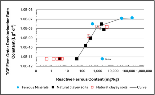
Figure 1: First-order rate constants for abiotic reductive dechlorination of TCE under anaerobic conditions. Circles are data from Schaefer
et al., 2021
[4], filled squares from Schaefer
et al., 2018
[5], and Schaefer
et al., 2017
[6], and open squares from Schaefer
et al., 2025
[1].
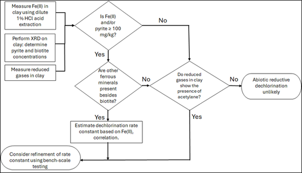
Figure 2: Flowchart diagram of field screening procedures
The recommended approach builds upon the methodology and findings of a recent study[1], emphasizing field-based and analytical techniques to quantify abiotic first-order reductive dechlorination rate constants for PCE and TCE in clayey soils under anoxic conditions. Key components of this evaluation are listed below:
- Zone Identification: The focus of the investigation should be to delineate clayey zones adjacent to hydraulically conductive zones.
- Ferrous Mineral Quantification: Assess ferrous mineral context in clay via 1% HCl extraction at ambient temperature over a 10-minute interval.
- Mineralogical Characterization: Conduct XRD analysis with the specific intent of identifying the presence of pyrite and biotite.
- Reduced Gas Analysis: Measurement of reduced gases such as acetylene, ethene, and ethane concentrations in clay samples. Gas-tight sampling devices (e.g., En Core® soil samplers by En Novative Technologies, Inc.) should be used to ensure sample integrity during collection and transport.
Clay samples should be collected within a few centimeters of the high-permeability interface, with optional additional sampling further inward. For mineralogical analysis, a defined interval may be collected and subsequently subsampled. To preserve sample integrity, exposure to air should be minimized during collection, transport, and handling. Homogenization should occur within an anaerobic chamber, and if subsamples are required for external analysis, they must be shipped in gas-tight, anaerobic containers.
Estimation of the abiotic reductive first-order rate constant for PCE and TCE is based on the “reactive” ferrous content in the clay. Reactive ferrous content (Fe(II)r) is estimated as shown in Equation 1:
- Equation 1: Fe(II)r = DA + XRDpyr - XRDbiotite
where DA is the ferrous content from the dilute acid (1% HCl) extraction, XRDpyr is the pyrite content from XRD analysis, and XRDbiotite is the biotite content from XRD analysis[1].
Abiotic dechlorination is unlikely to contribute to mitigating contaminant back-diffusion when reactive ferrous iron (Fe(II)r) concentrations are below 100 mg/kg (Figure 1). For Fe(II)r above 100 mg/kg, the first-order rate constant for PCE and TCE reductive dechlorination can be estimated using the correlation shown in Figure 1[5][7]. The rate constant exhibits a strong positive correlation with the logarithm of reactive Fe(II) content (Pearson’s r = 0.82), with a slope of 4.7 × 10⁻⁸ L g⁻¹ d⁻¹ (log mg kg⁻¹)⁻¹.
Figure 2 presents a decision flowchart designed to evaluate the significance and extent of abiotic reductive dechlorination. By applying Equation 1 to the dilute acid extractable Fe(II) plus measured mineral species data from clay samples, the reactive ferrous iron content (Fe(II)r) can be quantified, enabling a streamlined assessment of the extent to which abiotic processes are contributing to the mitigation of contaminant back-diffusion.
If Fe(II)r is ≥ 100 mg/kg, a first-order dechlorination rate constant can be estimated and subsequently used within a contaminant fate and transport model. However, if acetylene is detected in the clay, even with Fe(II)r less than 100 mg/kg, then bench-scale testing using methods similar to those described in a recent study[1] is recommended, as such results would likely be inconsistent with those shown in Figure 1, suggesting some other mechanism might be involved, or that the system mineralogy might be more complex than anticipated. Even if Fe(II)r ≥ 100 mg/kg, confirmatory bench-scale testing may be conducted for additional verification and to refine estimation of the abiotic dechlorination rate constant.
Summary and Recommendations
The approach outlined above is intended to serve as a generalized guide for practitioners and site managers to cost-effectively determine the extent to which beneficial abiotic reductive dechlorination reactions are likely occurring in low permeability (e.g., clayey) zones. This approach may be contraindicated if co-contaminants are present. It is currently unclear whether other classes of potentially reactive chemicals, such as trinitrotoluene (TNT) or chlorinated ethanes, could interact competitively with PCE and TCE.
In addition, it remains unclear how other classes of compounds such as per- and polyfluoroalkyl substances (PFAS) may interact or sorb with ferrous minerals and potentially inhibit abiotic dechlorination reactions. Coupling these recommended activities with conventional site investigation tasks would provide an opportunity to perform many of the up-front screening activities with minimal additional project costs. It is important to note that the guidance proposed herein pertains to particularly low permeability media. Sites with complex or varying lithology, where the mineralogy and/or redox conditions may vary, might require evaluation of multiple samples to provide appropriate site-wide information.
References
- ^ 1.0 1.1 1.2 1.3 1.4 Schaefer, C.E., Tran, D., Nguyen, D., Latta, D.E., Werth, C.J., 2025. Evaluating Mineral and In Situ Indicators of Abiotic Dechlorination in Clayey Soils. Groundwater Monitoring and Remediation, 45(2), pp. 31-39. doi: 10.1111/gwmr.12709
- ^ Falta, R., and Wang, W., 2017. A semi-analytical method for simulating matrix diffusion in numerical transport models. Journal of Contaminant Hydrology, 197, pp. 39-49. doi: 10.1016/j.jconhyd.2016.12.007 Open Access Manuscript
- ^ Kulkarni, P.R., Adamson, D.T., Popovic, J., Newell, C.J., 2022. Modeling a well-charactized perfluorooctane sulfate (PFOS) source and plume using the REMChlor-MD model to account for matrix diffusion. Journal of Contaminant Hydrology, 247, Article 103986. doi: 10.1016/j.jconhyd.2022.103986 Open Access Manuscript
- ^ Schaefer, C.E., Ho, P., Berns, E., Werth, C., 2021. Abiotic dechlorination in the presence of ferrous minerals. Journal of Contaminant Hydrology, 241, 103839. doi: 10.1016/j.jconhyd.2021.103839 Open Access Manuscript
- ^ 5.0 5.1 Schaefer, C.E., Ho, P., Berns, E., Werth, C., 2018. Mechanisms for abiotic dechlorination of trichloroethene by ferrous minerals under oxic and anoxic conditions in natural sediments. Environmental Science and Technology, 52(23), pp.13747-13755. doi: 10.1021/acs.est.8b04108
- ^ Schaefer, C.E., Ho., Gurr, C., Berns, E., Werth, C., 2017. Abiotic dechlorination of chlorinated ethenes in natural clayey soils: impacts of mineralogy and temperature. Journal of Contaminant Hydrology, 206, pp. 10-17. doi: 10.1016/j.jconhyd.2017.09.007 Open Access Manuscript
- ^ Borden, R.C., Cha, K.Y., 2021. Evaluating the impact of back diffusion on groundwater cleanup time. Journal of Contaminant Hydrology, 243, Article 103889. doi: 10.1016/j.jconhyd.2021 Open Access Manuscript
See Also

