Difference between revisions of "Injection Techniques for Liquid Amendments"
m (1 revision imported) |
|||
| (3 intermediate revisions by the same user not shown) | |||
| Line 2: | Line 2: | ||
<div style="float:right;margin:0 0 2em 2em;">__TOC__</div> | <div style="float:right;margin:0 0 2em 2em;">__TOC__</div> | ||
'''Related Article(s):''' | '''Related Article(s):''' | ||
| + | *[[Bioremediation - Anaerobic Secondary Water Quality Impacts]] | ||
| + | *[[Chemical Oxidation (In Situ - ISCO)]] | ||
*[[Chemical Reduction (In Situ - ISCR)]] | *[[Chemical Reduction (In Situ - ISCR)]] | ||
| − | |||
| − | |||
| − | ''' | + | |
| + | '''Contributor(s):''' [[Thomas Krug]] | ||
Latest revision as of 21:11, 27 April 2022
Many different types of amendments can be used for remediation of contaminants in soil and groundwater. A critical requirement for successful remediation is getting amendments in contact with the contaminants to be treated. Whether the amendments are promoting biodegradation, chemical reduction, chemical oxidation, or changing the geochemistry to sequester metals, effective distribution of amendments is a necessity. Geology, hydrogeology, and contaminant distribution are all components of a conceptual site model (CSM) and the development of an accurate CSM is a critical step in developing any remedial plan involving amendments. General approaches for injection and distribution of aqueous amendments include: (1) active injection with continuous recirculation of groundwater; (2) semi-passive injection with periodic recirculation of groundwater; and (3) passive or direct injection without recirculation of groundwater.
Related Article(s):
- Bioremediation - Anaerobic Secondary Water Quality Impacts
- Chemical Oxidation (In Situ - ISCO)
- Chemical Reduction (In Situ - ISCR)
Contributor(s): Thomas Krug
Key Resource(s):
- Delivery and Mixing in the Subsurface: Processes and Design Principles for In Situ Remediation[1]
- In Situ Bioremediation of Perchlorate in Groundwater[2]
Introduction
Amendments can be injected and distributed to: (a) provide direct contact with contaminants, or (b) create a biological or chemical treatment zone or barrier in the path of chemicals moving in groundwater that allows for amendment contact as contaminated water moves through the treatment zone or barrier.
Designing an effective amendment distribution program requires an understanding of the impacted site geology and hydrogeology. Knowing where to place the amendments requires an understanding of the current distribution of contaminants and what may happen in the future if effective source control measures are not put in place[1].
Distribution of amendments into fine geological material such as silts and clays is challenging because groundwater flow is very low. Fortunately, evaluations of different methods of injecting amendments into clay exists[3], and ESTCP is funding a promising new technology, electro-kinetic (E-K) amendment distribution, which involves enhancing the distribution of amendments in clay units by applying a direct current (DC) electrical field[4][5].
Amendments for remediation may be:
- soluble in water (e.g., electron donors such as alcohols or sugars, chemical oxidants such as sodium permanganate, or chemical reductants such as ferrous sulfate or sodium sulfide),
- emulsions in water (e.g., emulsified vegetable oil),
- very fine nano-scale particulates in suspension (e.g., nano-scale zero-valent iron [nano-ZVI]),
- larger particulates in suspension (e.g., micro-scale ZVI), or
- large solid materials (e.g., granular ZVI, limestone, or mulch) that are placed in the subsurface using an excavated trench method to form a permeable reactive barrier (PRB).
Soluble amendments can be injected easily and will distribute more widely in the subsurface in sand and sandy silt units. This allows for easy injection, but the amendments may not stay in the target injection areas for long periods of time if they continue to travel with groundwater flow after injection.
Emulsions can be injected and distributed some distance in the subsurface, but their mobility is often limited by chemistry of the emulsion and their interactions with geological media. Nano- or micro-scale solids in suspension will not move as far from the point of injection as soluble amendments so distribution may be more challenging. However, solids in suspensions tend to stay closer to the injection location post injection, which may be beneficial for longer-term treatment. Particulates in suspension can be injected using aggressive higher energy methods such as hydraulic or pneumatic injection and typically do not move from their point of injection unless they break down into soluble constituents.
Large solid materials are typically not injected, but are more often placed into an excavated trench perpendicular to the direction of groundwater flow in a configuration referred to as a PRB. This article focuses on the distribution of soluble, emulsions, and nano- or micro-scale solids in suspension into geological material such as sand and sandy silt where is it possible to move groundwater as part of an amendment injection and distribution.
Amendment Injection and Distribution Methods
Here, we describe three approaches to amendment injection and distribution in the subsurface along with their advantages and disadvantages. Within each approach, many variations of well configuration, injection duration, injection flowrates, electron donor concentrations, cycle times, and other operational details are possible. The selection of the approach, wells configuration, and operating details will depend upon the site conditions, remedial objectives, availability of operators, and other site specific factors that impact the design. As part of the design process, it is necessary to develop an accurate conceptual site model (CSM) incorporating the geology, hydrogeology, contaminant distribution, and groundwater geochemistry. Numerical groundwater flow modeling can provide a valuable tool in evaluating various approaches and design details to develop an optimal design for the system.
1) Active Amendment Injection
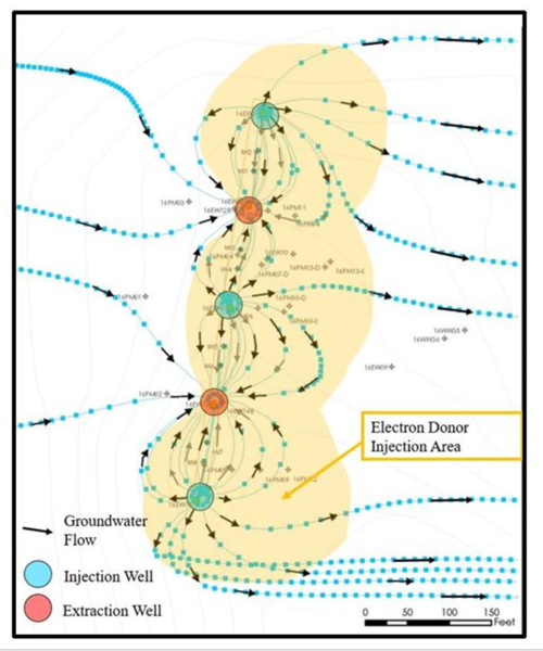
Active amendment injection processes typically involve continuous extraction of groundwater, amending this water, and reinjection of the amended water (Fig. 1). The extraction and reinjection well configuration is normally set up so that injected amended groundwater is drawn towards the extraction well to maximize and control the distribution of amendment in the subsurface and to avoid pushing impacted groundwater away from the treatment area. This process allows for better control of the dose of amendment because the target concentration of amendment can be added to the water being reinjected. This reduces the potential for negative impacts of high concentrations of amendment that can occur with semi-passive and passive approaches. The down side of active recirculation systems is that the injection well is operated on a continuous basis and this type of operation is more likely to lead to fouling of the injection well or wells. A steady supply of electron donor to the injection wells encourages the growth of biomass in and around the injection wells and leads to increased biofouling. Regular maintenance and fouling control measures are normally required to keep the injection wells operating[2].
2) Semi-Passive Amendment Injection
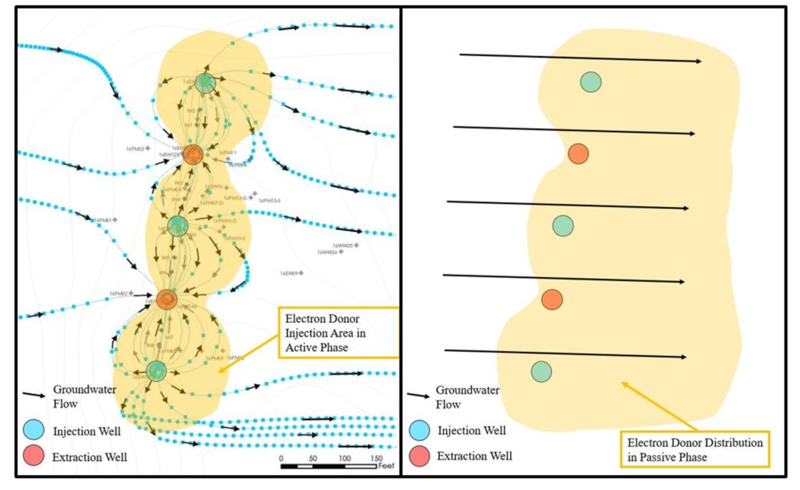
Semi-passive amendment injection processes involve periodic extraction of groundwater, addition of amendment to this water, and reinjection of the amended water. The groundwater is recirculated on a periodic basis (e.g. every few weeks to months, Fig. 2 left panel)[2], to distribute higher concentrations of amendment that will provide the appropriate dose of amendment until the next cycle of addition. Semi-passive systems are often set up to distribute amendment in a line perpendicular to the direction of groundwater flow.
Once the amendment is distributed, the injection and recirculation process is shut down and the natural flow of groundwater carries groundwater through the zone where the amendment is present (Fig. 2, right panel). Contaminants in the groundwater flowing through this zone are treated as they contact the amendments.
This process may require higher doses of amendment to be added to the subsurface than with the active approach, which can result in negative impacts of higher concentrations of amendment. However, these impacts are often mitigated downgradient of the injection area as background geochemical conditions are re-established. One of the benefits of the semi-passive approach is that there is less potential for fouling of the injection wells because amendment is added only on a periodic basis. Operating costs for semi-passive system are lower than active approaches because less maintenance is required to avoid fouling, and the system is operated on a periodic rather than a full time basis[2].
3) Passive Amendment Injection
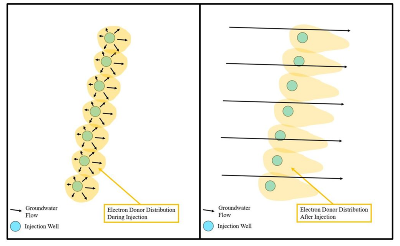
Passive amendment injection involves injection at discrete points to form a treatment zone without recirculation of groundwater. The injection point configuration is normally set up with one or more lines of injection points in a line perpendicular to the direction of groundwater flow (Fig. 3, left panel). Injection may be repeated on a periodic basis, and will provide the appropriate amount of amendment until the next cycle of amendment addition. The number of injection points required to distribute amendment is more than for semi-passive systems because groundwater is not circulated to distribute the amendment between injection and extraction points. Following injection, the natural flow of groundwater carries groundwater through the zone where the amendment is present (Fig. 3, right panel).
Passive injection systems require more wells than active and semi-passive systems and are often more suited for treatment of shallow groundwater, where the costs to install injection wells or points are less than for deeper groundwater. Active and semi-passive systems require fewer wells and are therefore more cost effective for deeper groundwater when individual wells are more expensive to install. The passive approach requires even higher doses of amendment to be added to the subsurface than with the active or semi-passive approaches, which can result in greater negative impacts of high concentrations of amendments such as more highly reducing conditions with enhanced in situ bioremediation (EISB) that can mobilize metals such as iron, manganese and arsenic. The passive injection approach requires many more discrete injection points than for the semi-passive approach and can be more expensive when the target treatment interval is deep and the cost to install wells or injection points is high[2].
Relative Advantages of Different Approaches
Active and semi-passive approaches require fewer wells than passive injection approaches and tend to be more cost effective for deep groundwater contamination where the cost to install individual wells is high. Active approaches maintain a stable concentration of amendment and are favored when impacts on water quality of high periodic spikes in the concentration of amendments are of concern. Active approaches do have the disadvantage of high operating costs including biofouling control. Semi-passive approaches also require fewer wells than passive injection, but typically have lower operation costs than active approaches. Passive approaches require more wells or injection points than active or semi-passive approaches, but can be cost effective for shallow groundwater where the cost of individual injection points is low. Passive approaches are not favored in the situations where large spikes in amendment concentrations can have negative impacts on water quality[6].
Example case studies of each type of amendment method are available for interested remediation professionals[2].
References
- ^ 1.0 1.1 Kitanidis, P.K. and McCarty, P.L. eds., 2012. Delivery and Mixing in the Subsurface: Processes and Design Principles for In Situ Remediation (Vol. 4). Springer Science & Business Media. 325 pgs. doi: 10.1007/978-1-4614-2239-6
- ^ 2.0 2.1 2.2 2.3 2.4 2.5 Stroo, H.F., and Ward, C.H., 2009. In situ bioremediation of perchlorate in groundwater. SERDP/ESTCP Remediation Technology Monograph Series, Springer Science and Business Media, LLC. Book on Springer Website
- ^ Christiansen, C.M., Damgaard, I., Broholm, M., Kessler, T., Klint, K.E., Nilsson, B. and Bjerg, P.L., 2010. Comparison of delivery methods for enhanced in situ remediation in clay till. Groundwater Monitoring & Remediation, 30(4), 107-122. doi: 10.1111/j.1745-6592.2010.01314.x
- ^ Mao, X., Wang, J., Ciblak, A., Cox, E.E., Riis, C., Terkelsen, M., Gent, D.B. and Alshawabkeh, A.N., 2012. Electrokinetic-enhanced bioaugmentation for remediation of chlorinated solvents contaminated clay. Journal of Hazardous Materials, 213, 311-317. doi: 10.1016/j.jhazmat.2012.02.001
- ^ Cox, E., 2016. Electrokinetic-Enhanced (EK-Enhanced) Amendment Delivery for Remediation of Low Permeability and Heterogeneous Materials. Environmental Security Technology Certification Program (ESTCP) Ongoing Project ER-201325. ER-201325
- ^ Stroo, H.F., Leeson, A., Ward, C.H., (Eds.), 2013. Bioaugmentation for Groundwater Remediation. SERDP/ESTCP Remediation Technology Monograph Series. Series Editor: C. Herb Ward. Springer Science and Business Media.
See Also
- Battelle Memorial Institute and NAVFAC Alternative Restoration Technology Team, 2013. Best Practices for Injection and Distribution of Amendments. Technical Report prepared for Naval Facilities Engineering Command (NAVFAC). TR-NAVFAC-EXWC-EV-1303
- Development of Design Tools for Planning Aqueous Amendment Injection Systems, ESTCP-SERDP Project ER-200626


